
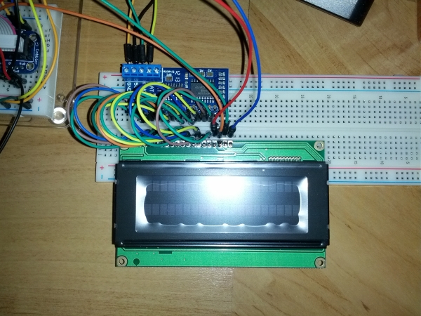
Here, i want to testing between 16×2 LCD screen with Raspberry Pi. As you can see from my previous blog, the circuit have been construct based on this connection. If there had no problem with all the connection, I will proceed to combine it with female wire and jumper.
 I choose fritzing because I can create a test specification via GPIO port using Raspberry Pi. I think that trying to integrate equipment into Fritzing would be easy and fast result to make sure the connection is right or not. First, just choose the core part for input and output. Then, using breadboard view, the circuit also can be export to schematic and PCB layout.
The figure above show my first attempt to make the project more readable and its how Fritzing diagram shows on breadboard view.
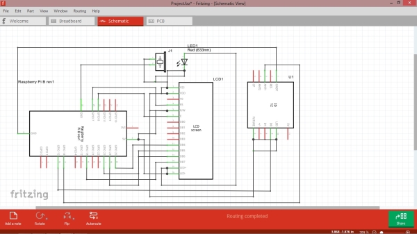
The schematic view on the above is connection between RFID, Raspberry Pi, LCD Screen, buzzer and LED. After the schematic view shows there is no wrong on the each part of the circuit, then I will proceed on my wiring.
This is what I ended up with (click for big). The routing for connection is in mess because there have to many connection between the wires.
Source: (Week 13) Testing with 16×2 LCD screen and Raspberry Pi using Fritzing