
Introduction
The XMOS startKIT from Farnell (or Newark) is a very low cost (£12 including VAT) processor platform that works well with the Raspberry Pi. Together is possible to construct robotics applications with almost no soldering required.
The XMOS startKIT is a near-credit-card sized board with an XMOS chip on it with multiple ‘XMOS cores’ that can be programmed in C. XMOS technology allows things to run in parallel at high speed with low jitter. These are exactly the characteristics which could be ideal for robotics applications.
Together with some code to run on the XMOS startKIT board and on the Raspberry Pi (RPI), the boards are used to construct a simple compact mobile platform (I’m going to call it XMP, XMOS Mobile Platform instead of a robot from now on in the XMOS spirit of preceding everything with ‘X’).
Although the XMP-1 is not much of a robot until it has some sensors and more programing, it could be extended in future for robotics experiments. The XMP-1 uses low cost off-the-shelf standard hardware and no exotic tools beyond screwdriver, wire-cutters and pliers.
This post covers communication between the RPI and XMOS board using a serial peripheral interface (SPI) interface and how to construct up the XMP-1 and control it from a web browser.
The video here shows XMP-1 being taught a route; the first attempt at using it! It would benefit from a better user interface. XMP-1 can move quite fast, but I took it easy here on a low speed. On the right is the browser control, and at the bottom is the console output, just generating some keep-alive and status messages to see what's occurring.
This next video below shows the XMP-1 attempting to play back the route and causing suffering and pain along the way. My low-cost continuous rotation servos (which are being used to drive the wheels) were not very good, and XMP-1 has no sensors yet.
A bit more detail
This post is actually part 2 of some XMOS startKIT experiments. Part 1 contains the XMOS introduction, terminology, architecture and a quick getting started guide with example programs. If you're interested in the technology then it may help to follow part 1 first, so that this part 2 makes more sense. This part 2 is intended to construct a simple framework for high speed communications between the Raspberry Pi and the XMOS startKIT board. The framework should be general purpose enough to be able to use for many projects (robotics was not my intention). The XMP-1 is really just a by-product, in the desire to test out the Raspberry Pi to XMOS board communications. It is recorded here in case it is useful. (Note, there is also a part 3 entitled XMOS startKIT: XMOS and Raspberry Pi Oscilloscope XAE 1000 which reuses the SPI capability discussed is this post, and introduces how to use the analog to digital converter (ADC) that is present in the XMOS chip, and how to perform real-time graphics in a web browser).
If you’re only interested in constructing and using XMP-1 then you can just take the code at the bottom of the post, compile and store to Flash (as described in part 1) on the XMOS startKIT board and the Raspberry Pi, and just follow the sections that describe XMP-1 hardware assembly, skipping all other content here. If you’re interested in controlling any hardware using the Raspberry Pi and a web browser then some of the code here can be reused. But, to get most out of the Raspberry Pi and XMOS startKIT combination the remainder information here may be useful if you’re new to the startKIT.
Solution Overview – Hardware and Software
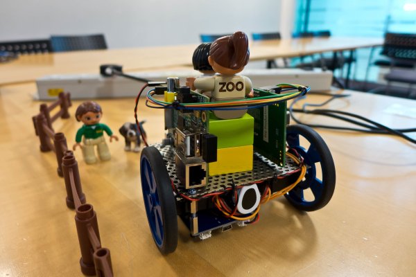
Here is a photo of the completed XMP-1 being charged up. For outdoor use, I used a 802.11 hotspot type device (MiFi), running the browser on a mobile phone.
The diagram below shows the approximate layout of the bits and pieces as viewed from the rear of XMP-1. You can see that it’s pretty basic – XMP-1 was just a quick experiment.
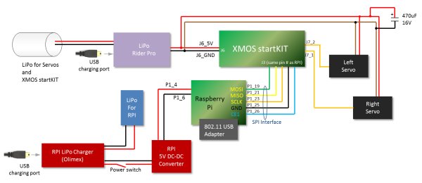
The Raspberry Pi (RPI) is used to handle all network activity. It runs a small web server and most of the code is written in JavaScript on a Node.js platform. The RPI communicates motor control speeds (actually continuous rotation servos were used for XMP-1) over a serial interface (SPI) to the XMOS startKIT board. The XMOS startKIT is responsible for feeding pulse width modulation (PWM) signals to the motors.
The RPI is connected to the network using an 802.11 WiFi USB adapter.
The full wiring diagram is shown here. The hardware and construction is described later.
The diagram below shows the software that will be implemented on the RPI and on the startKIT. It looks a lot, but it isn’t and can be broken down into small parts which will be described further below. As mentioned the entire source code is at the bottom of this post so it could be used without any modification if desired.
In brief, the green block handles the web interaction and determines the speed and direction of the motors based on the user input. The green block provides a web page (index.html) to the user that incorporates the user interface. The xmos_servo program is a small bit of software written in C that translates the desired speed/direction into serial peripheral interface bytes of data that are sent to the startKIT. The startKIT software is divided into three parts that run simultaneously on separate XMOS cores. The spi_process converts the SPI signals into data that is stored in an array. The data_handler code inspects the array to decide what to do (the only conclusion it makes today is to manipulate the servos). The servo_handler process outputs a pulse stream to the servos, so that they can rotate at the desired speed. All these blocks are explained in more detail further below.
Serial Peripheral Interface (SPI)
SPI relies on four wires known as SS, SCLK, MISO and MOSI and an assignment of master and slave for the two devices involved in the communication. In the case of the RPI and XMOS board, the RPI is the master device and is responsible for generating the clock signal. The RPI transmits data on the MOSI wire, and received data on the MISO wire. This means that the SPI interface can transfer data in a bidirectional fashion at the same time. In practice if one-way data is required then either the MOSI or the MISO signal can be ignored depending on the direction of interest.
The oscilloscope screenshot here (individual signals and the automated SPI decode from a Tektronix MSO2024B oscilloscope) shows an example of SPI communication using the Raspberry Pi. SPI can be configured in a few ways; you can see in this example that three bytes of data were transferred from the master (RPI) to the slave (XMOS board) and that they were 0x02, 0x00 and 0x10, and either no data or 0x00, 0x00, 0x00 was transferred from the slave to the master simultaneously.
The SS wire is a chip-select signal (active low). The RPI has two pins on it’s 26-way connector that could be used for SS; they are shown circled in blue in the diagram below, marked CE0 and CE1. This means that the RPI can talk to two SPI slave devices if desired. In this case, only one of the CE pins was used – I picked CE1.
ontrolling Hobby Servo Motors
Hobby servo motors generate a movement based on an input signal. They usually rotate less than one full revolution. Usually a hobby servo will rotate within a range of about 180 degrees. The output shaft can be connected to (say) linkages to make wheels turn full left or full right (or anything in between) based on the input signal.
The diagram below shows the internals of a typical hobby servo (taken from this site). On the left (in blue) is a conventional DC motor. It is geared down a lot, and the final shaft can be seen on the right connected to a blue arm which could be connected to a wheel steering mechanism for example. Underneath the final shaft will be a potentiometer, and that provides feedback about the exact position of the final shaft. A hobby servo is therefore a closed loop system and can self-correct if the arm gets accidentally knocked away from the desired position.
Hobby servos typically have three connections; 0V, 5V and Signal. The signal wire is a digital input to the servo and it requires a PWM signal. The size of the pulse width determines the angle that the shaft will move to. The PWM signal needs to repeat every 20 msec, and a pulse width of 1.5msec will result in the shaft moving to a centered position. A width of 1msec will move the servo fully in one direction, and a width of 2 msec will move the servo fully in the other direction (further below there will be some oscilloscope traces of servo control).
There is a type of modified servo known as a ‘continuous rotation’ servo. It is a modified servo where the potentiometer is removed along with any end-stops, and the circuitry is persuaded into thinking that the servo is still in the centered position. Sending PWM with a pulse width other than 1.5msec will make the mechanism rotate in the clockwise or anticlockwise direction at a speed that depends on the pulse width. The XMP-1 uses two continuous rotation hobby servos, one for each wheel. They are not an optimal way of obtaining controlled motion (XMP-2 will use DC brushed motors) since they are being used for a purpose different from the original intent for hobby servos, but they have the advantage that they can be controlled by a digital logic signal and they do not require any external H-bridge circuit.
Hobby servo wires can be color-coded differently depending on manufacturer. Usually the center wire is red, and it goes to +5V. The black or brown wire is 0V. The white or yellow wire is the PWM signal input.
Starting development – Connecting up the boards
In order to develop the software, the RPI and startKIT were connected up using a ribbon cable and IDC connector assembly – these can be assembled using a vice or purchased ready-made. For a self-assembled version it is worth buying an extra IDC connector for use as a debug connector at the center of the cable, to make life easier when probing signals with a multimeter or scope.
Implementing SPI (spi_process) on the XMOS startKIT
Using the XMOS development environment (xTIMEcomposer) was covered in part 1. The screenshots below show the Windows version of xTIMEcomposer, but the Linux version looks identical (and possibly the Mac version may look similar too).
At this point you can right-click on the SPI Slave Function Library in the xSOFTip lab and import the library into the workspace. I’m no expert on xTIMEcomposer so I’m probably using it wrong here, but the source code and header file for the library appeared in a separate folder in the Project Explorer (shown circled in blue below):
The files were required to be in the spi-test folder (so that they appear as shown circled in green above) so to achieve that I manually copied the spi_slave.h and spi_slave.xc files from module_spi_slave/src folder into the spi-test/src folder using Windows Explorer.
The software uses the concept of ports to control output or to read input. There is a mapping between these logical ports and the physical mapping out to the pin on the chip. The mappings can be altered in certain combinations (See figure 3 in the Introduction to XS1 ports PDF document).
Input/Output ports on XMOS devices can be 1, 4, 8, 16 or 32-bit wide. When designing with the part, you may wish to allocate certain functions to 1-bit ports, or other functions to multi-bit ports, and so figure 3 will be very useful to determine which ports and pins to use.
With the SPI slave code now in the spi-test/src filder, this code was modified slightly. The library code makes an assumption that the ports that are being used for the SPI interface are all 1-bit ports, whereas the Raspberry Pi SPI SS pin (CE1) is connected to a 32-bit port on the XMOS board. Figure 8 from the startKIT Hardware Manual PDF document is shown below. In the center in green you can see the 2×13-way header that connects between the XMOS board and the Raspberry Pi. On the left and right in blue are the physical pin names on the chip (X0D0,, X0D11, etc). The pin highlighted values are the logical port numbers. P1A, P1D and so on are single-bit ports. P32A1 is the first binary digit of a 32-bit port
Quite a few changes were made to the SPI library and the entire code is attached to the post, so only some snippets of code will be described here, there is no need to copy/paste, the full code attached at the end of this post can be used.
The SPI interface on the XMOS device is initialized as shown here. It is explained further below.
- void spi_slave_init(spi_slave_interface &spi_if)
- {
- int clk_start;
- set_clock_on(spi_if.blk);
- configure_clock_src(spi_if.blk, spi_if.sclk);
- configure_in_port(spi_if.mosi, spi_if.blk);
- configure_out_port(spi_if.miso, spi_if.blk, 0);
- start_clock(spi_if.blk);
- return;
- }
As mentioned in the Part 1 post, I/O can be clocked in and out of the XMOS device at precise times. In the code above, the set_clock_on function (defined in the XMOS xs1.h header file) is used to turn on one of the built-in clocking mechanisms in the XMOS chip. The diagram below (from the Introduction to XS1 Ports document) shows this mechanism in yellow. The configure_clock_src function is used to select an external clock (shown in blue in the diagram). It will be connected to the SCLK pin on the Raspberry Pi. The configure_in_port and configure_out_port functions are used to tie ports to the clocking mechanism. Both the MOSI and MISO signals (shown in green below) are configured to be tied to the clocking mechanism.
The way serial data is handled on XMOS devices is really neat. The code here is explained further below. First, a structure is used to contain details about the ports that are desired to be used as the SPI interface.
- typedef struct spi_slave_interface
- {
- clock blk;
- in port ss;
- in buffered port:8 mosi;
- out buffered port:8 miso;
- in port sclk;
- } spi_slave_interface;
The interesting lines above are the ones that refer to port variables mosi and miso. They have been declared as type port:8. If the variables are assigned 1-bit port addresses, then the XMOS device will automatically de-serialize the 1-wire stream of bits into 8-bit values.
It makes the rest of the SPI code really simple. Here is the code that manages SPI data input from the Raspberry Pi:
- void spi_slave_in_buffer(spi_slave_interface &spi_if, unsigned char buffer[], int num_bytes)
- {
- unsigned int data;
- unsigned int vlen=0;
- clearbuf(spi_if.miso);
- clearbuf(spi_if.mosi);
- for (int i = 0; i < num_bytes; i++)
- {
- spi_if.mosi :> data;
- data=data<<24;
- buffer[i]=bitrev(data);
- if (i==2)
- {
- vlen=(((unsigned int)buffer[1])<<8) | (unsigned int)buffer[2];
- if (vlen==0)
- break;
- }
- if (i >= vlen+2)
- {
- break;
- }
- }
- }
In the code above, you can see that there is a for loop, and within the loop the line spi_if.mosi :> data; is used to read 8 bits of information on the MOSI line into the variable called data.
The next two lines are used to flip the bits around within the byte and then the data is stored in a buffer array.
The next few lines need some explanation; they are related to the desired protocol. It was intended to create some general-purpose code that could be used for many things, not just XMP-1. If the Raspberry Pi sends data to the XMOS startKIT board, the XMOS board needs to know how many bytes of data to expect. This could be hard coded but it would be inflexible.
It was decided to use a very simple ‘tag (or type), length, value’ (TLV) protocol. The first byte that the Raspberry Pi must transmit is a tag or identifier in the range 0-255 (i.e. one byte). It is up to the user to decide what the values represent. For example, a value of 1 could mean “set motor speed” and a value of 2 could mean “set headlight brightness intensity”. The second two bytes are a 16-bit value that indicate how many value (i.e. data) bytes are to follow. I decided to limit this to 4kbyte (4096 bytes) which should meet many use-cases but the actual value can be changed by adjusting a BUFLEN definition in the code.
Therefore the minimum number of bytes sent on the SPI interface are three (tag, and a length of 0x0000) and the maximum are 4099 which is a tag and a length of 0x1000 (this is 4096 in hexadecimal) and 4096 data bytes.
The protocol was refined slightly, so that an odd tag number means that the Raspberry Pi expects a response back in the following SPI communication that it initiates after the current TLV stream is complete, and an even tag number means that the Raspberry Pi expects no response back.
This is a very basic protocol but it should meet many usual requirements. It is also explained in the table below where the blue number is the SPI byte index into the receiving 4099-byte buffer.
Going back to the earlier code snippet it can be seen that the next few lines check the buffer[1] and buffer[2] contents on the fly while the SPI data is being received. The contents are expected to be the length as seen in the diagram above (see blue buffer index). As soon as the code has determined the remainder length, it will accept exactly that number of Data bytes, and then the routine exits.
That covers SPI input to the XMOS board on the MOSI line. SPI output from the XMOS device on the MISO line operates in a similar manner, checking the the length simultaneously on the MOSI line on the fly again, so that the function can exit as soon as the requested number of bytes has been transferred.
Inter-Process Communication
Now that SPI was figured out and a protocol had been implemented to exchange variable length data in either direction up to 4096 bytes long, some consideration was given to the main body of the program. It was clear that an XMOS core would be dedicated to handling the SPI task, but the rest of the code may need to reside in one or more additional XMO Scores.
In part 1, it was described how tasks run in parallel on different XMOS cores, and how the tasks can communicate to each other by pushing values into channels. There is another way of communicating between cores and it uses the concept of “transactions via interfaces” rather than channels. It is more flexible because you can send multiple variables of different types from one XMOS core to another. The transaction types are defined much like a C function prototype. This all becomes much clearer by looking at an example.
For instance, if an application had a task that controlled a display, then a sending task may want to turn the display on or off, or it may want to plot a pixel. The interface definition for the communication between the two XMOS cores could look something like this:
- interface program_display
- {
- void backlight(int state, int color) ; // transaction type 1
- void plot(int x, int y, int color); // transaction type 2
- };
Interface communication is unidirectional, so if the display wanted to send information such as (say) the touchscreen state, then another interface would need to be used in the other direction. From this it is clear that interfaces have a client and server end. The diagram here shows two XMOS cores (in purple), two interfaces (in gray) and the first interface (called program_display) allows two different types of transactions to occur (in blue) across the program_display interface.
The great thing about using interfaces and transaction types is that, much like C function prototypes, you can have return values and you can pass references to variables, so that even though the communication is always initiated by the client end of the interface, data transfer can occur both-ways. Another very interesting feature not shown on the diagram is the ability for the server end to be able to send a ‘notification’ to the client end. This can be a signal to the client to issue a transaction in the usual manner, to perhaps retrieve some data. This feature will be used in the XMP-1 code. So, more information on exactly how to code the interfaces and send data and notifications will be explained further below.
Designing the IPC architecture to handle SPI content
The SPI interface handling has already been described. Now the content of the SPI messages needs to be presented to a task in a useful manner for subsequent processing. Armed with the knowledge about interfaces and transactions, it was possible to begin allocating functionality to separate XMOS cores and designing the inter-process communication to get to a general-purpose framework that would allow useful message content to be sent from the RPI to the XMOS board and vice-versa, and be processed.
The diagram here shows what was developed (a similar diagram as before, except now there is a time sequence from top to bottom).
When the Raspberry Pi desires to send a message to the XMOS board, the RPI will construct up the message into the TLV format described earlier. The information is then clocked out on the MOSI signal wire (shown in green at the top of the diagram above). Simultaneously the XMOS device needs to send something back, but since there is no information yet to send back, the MISO line can contain garbage or all zero values as shown in pink. The spi_process function will collect up the message into a buffer (an array of unsigned char) and then it will initiate a transaction to a separate data_handler XMOS core. The data_handler is responsible for processing the contents of the message and optionally sending back information to the spi_process XMOS core, so that any subsequent SPI exchange can send useful data back to the Raspberry Pi instead of garbage values.
The data could be sent between spi_process and data_handler by making a copy of the buffer. However instead it is possible to just pass a pointer to the buffer memory. One way this can be done is to ‘move’ control of the pointer and buffer memory locations from spi_process to data_handler. Once data_handler is done with the message inspection, it can move control back to spi_process using the return variable that is possible to use in transactions. This is why the diagram above has a transaction called array_data with a parameter defined as a moveable pointer and a return value defined as a moveable pointer too. This way, only one XMOS core has access to the buffer memory at any one time.
These are the interfaces that are used:
- interface to_rpi
- {
- void code(unsigned char c);
- };
- interface from_rpi
- {
- unsigned char* movable array_data(unsigned char* movable bufp);
- };
The spi_handler code allocates space for a buffer, and then passes control of the buffer to the data_handler code using the line buf=c.array_data(move(buf)) shown in the code here:
- void
- spi_process(interface to_rpi server s, interface from_rpi client c)
- {
- unsigned char storage[4099];
- unsigned char* movable buf=storage;
- …
- buf=c.array_data(move(buf));
- …
- select
- {
- case s.code(unsigned char c):
- if (c==SEND)
- {
- spi_slave_out_buffer(spi_sif, buf, 4099);
- }
- break;
- }
- }
The data_handler code obtains control of the buffer and then if any response is desired to be sent to the RPI on a subsequent SPI transaction, the buffer is populated with a response. Finally control of the buffer is passed back to the spi_handler process.
- void
- data_handler(interface to_rpi client c, interface from_rpi server s)
- {
- select
- {
- case s.array_data(unsigned char* movable vp) -> unsigned char* movable vq:
- // vq contains the data from SPI. We can do whatever we like with it here.
- // Any response is constructed up here too:
- vq[0]=0x22; // tag
- vq[1]=0x00; // length
- vq[2]=0x00; // length
- vq=move(vp); // pass the pointer control back to spi_process
- tosend=1;
- break;
- }
- if (tosend)
- {
- c.code(SEND); // send a code to spi_process so that it is aware there is data to send to RPI
- }
- }
 Earlier it was mentioned that if an odd tag value was sent by the RPI then this would be an indication that the RPI expected a response message from the XMOS startKIT board on the subsequent SPI exchange. This is implemented by both the spi_process and data_handler making a note that a return message is expected if the first byte received is an odd value. Once data_handler has finished constructing the return message in the buffer memory it moves the buffer pointer back to the spi_process XMOS core and also sends a code transaction which could contain a message such as “ready to send”. The spi_process XMOS core is now ready for any subsequent SPI exchange. If the data_process doesn’t want to send any message back to the Raspberry Pi (for example if the tag was even valued) then the code transaction is not sent (or a different code could be sent such as “not ready to send”).
In the graphic diagram earlier you can see that the subsequent SPI exchange did transmit data back to the Raspberry Pi on the MISO wire.
To summarize, the spi_process and data_process present a fairly general-purpose capability to exchange data bidirectionally between the RPI and XMOS board.
Implementing PWM (servo_handler) on the startKIT
To test out the general purpose architecture, it was decided to use it to control many devices. The devices ended up being hobby servos because they require very little electrical interfacing effort – no H-bridge or transistor driver is needed – and the servo input wire can be directly connected to an XMOS output pin. I didn’t have many servos, so although the code implements 8 servo control, only two were used for XMP-1.
The code could be modified to provide DC motor control too (with a suitable external H-bridge circuit).
It was decided to use a single XMOS core to handle the eight servos. The diagram below shows the total of three XMOS processes used in the solution. The new addition is the servo_handler task which is shown on the right. This task has an array that stores the current servo values. As soon as the task starts up, the values are initialized to a centered value (or standstill for a continuous rotation servo) and then every microsecond the task wakes up to check if the servo PWM signal needs adjustment. If it does then the servo port output is toggled. After 20msec the process repeats.
For more detail: XMOS startKIT Building an XMOS and Raspberry Pi Robot XMP-1