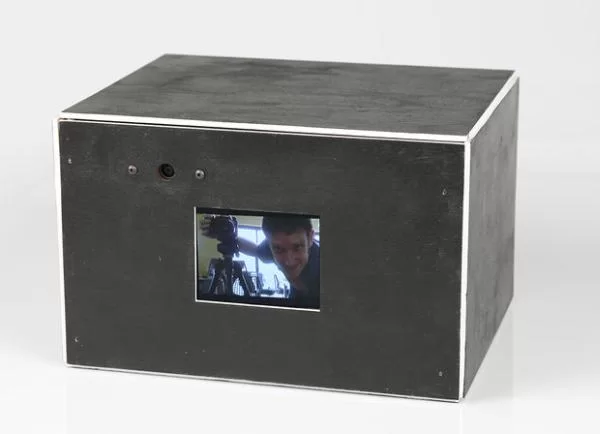
Black Box Timelapse is a simultaneous timelapse recorder and player, which I built using a Raspberry Pi. It is battery-operated and so I can bring it to different places and set it up.
Why not use an iPhone? Simple: the iPhone looks like a device and so people respond to it like a devie, rather than an art object, which invites curiosity.
Overview on How it works
The video is displayed on this small screen and essentially stacks images over time. You can also plug in an HDMI cable to a monitor or projector if you want to see it in a larger format.
It automatically runs when you plug it in or activate the battery. Right now, the camera takes a new images every 10 seconds and cycles after about 800 images, such that the timelapse will always show the last 2 hours of what happened in a space.
In version 2, this will be controlled with potentiometers, so that you control how often the camera will take images and how quickly it will cycle.
This Instructable will show you both the software configuration and software code as well as the physical fabrication steps I did to make this project come to life
Step 1: Basic Raspberry Pi set up
We’re going to make sure we have a few things in order.
First, make sure your Raspberry Pi is properly configured with the basic setup using my Ultimate Raspberry Pi Configuration Guide Instructable.
After this, we will want to make sure that we follow this Instructable on how to mount a USB Thumb Drive on the Raspberry Pi.
These two guides will make it so that we can save timelapse images onto a USB drive and that the Raspberry Pi will be easily configured. We will also add the ability to use the camera on the Raspberry Pi and later on, automatically launch a Python script upon startup.
Step 2: Gather components
These are the components I’m using, which took awhile to research and figure out.
– Raspberry Pi
– Small TFT monitor, which I ordered from Adafruit for $45.
– Rechargeable 12V battery, with USB output*
– USB battery that outputs 2A. Currently, I’m using this one from Adafruit, which has been reliable, thought a bit heavy
– small USB 3.0 dongle
– RCA male-to-male coupler
– Micro USB for running out to the battery
– Perf board with: 3-position switch, leads for recharging and GPIO.
– GPIO (not used for version 1)
* This 12V battery ended up having problems with the USB output. I was hoping to have one battery run the show, but the Raspberry Pi ended up spiking the power needs when the camera was taking a picture and then the battery would cause a voltage drop, forcing the Raspberry Pi to reboot
Step 3: Battery Charging Mechanism
The electronics portion of this Instructable isn’t as well-developed as I’d like. I’m going to improve upon this in the future.
What I ended up doing was making a perf board that includes a GPIO with an ADC chip to control the potentiometers. However, I ran out of time to write the software for potentiometers, so will have to come back to this. So, for the perf board, we are just using a charging circuit for the 12V battery.
This brand of battery has a the same input and output jack, so I rigged up a simple mechanism which has a three-position switch. In the up position, the 12V battery supplies power to the monitor via the video cables.
In the down position, it will look for the charger, as the female connector.
In the neutral or middle position, no power will be active.
I tie all the grounds together (video, battery, charger) and the switch will connect the positive wire of the battery to either to the video monitor, the charger or nothing.
The USB battery isn’t part of this circuit and has an on/off switch.
Step 4: Install Picamera and activate
We will be using the Picamera libraries, which provide a very easy-to-use Python interface into the camera module. Full details of the package are here.
First, we do some housekeeping. From the command prompt, do your standard updates and upgrades, type in:
sudo apt-get update
then:
sudo apt-get upgrade
you will see lines of Linux install code and will have to wait awhile.
Now, install the package itself with:
sudo apt-get install python-picamera
Finally, we want to enable the camera itself. Type in:
sudo raspi-config
This will bring a configuration menu, wh
ere you can Enable the camera, which is disabled by default. Enable the camera and reboot.
Step 5: Test Picamera
At this point, you’ll want to have the Pi hoo
ked into a monitor, rather than ssh.
Make sure your Raspberry Pi camera is properly connected to your Raspberry Pi. I keep referring to this video guide for proper orientation of the ribbon cable.
Create a simple Raspberry Pi preview script
nano cam_preview.py
now, type in this script:
—–
import time
import picamera
with picamera.PiCamera() as camera:
camera.start_preview()
time.sleep(2)
while True:
time.sleep(10)
—-
ctrl-X, return will save
run it:
sudo python cam_preview.py
What you should see is the camera showing a preview image.
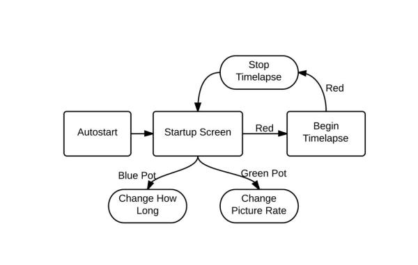
Step 6: Diagram code
This is the full flowchart of the code interaction. I wrote this out to help figure out how the interaction model will work.
Even though I didn’t use the pots for this version, the flowchart technique is super-helpful, especially when it comes down to working with the Raspberry Pi, which can be tedious to program.
Step 7: Write the Python
code
This didn’t take a super long time to do, but did take some wrangling.
Looking at my original flowchart, I followed most of the steps.
Everything is on GitHub, here.
Step 8: Setup Python code to auto-launch on startup
Using my Instructable: Launch Python script on startup, I built a launcher.sh script and edited the crontab to automatically start the Python code.
The escape key will exit the script.
Step 9: Make an internal camera mount
I based my camera mount on an existing STL model of a Raspberry Pi camera enclosure on Thingiverse.
Mine will be mounted inside the black box and needs to have “wings” so that it can be attached to the interior of the box.
Using 123D Design, I added these components and
then 3D printed the mount, attaching the camera inside and sealing the two pieces of the mount with epoxy.
Step 10: Design fabricated parts
I set up a basic design using Illustrator of what I want the Black Box Timelapse to look like. It consists of a monitor, a camera and inside, a Raspberry Pi and various batteries for mobile use.
The main idea is to:
(1) use as much digital fabrication techniques as possible, i.e. no saws and absolutely minimal sanding and touch-up work.
(2) make a hand-painted aesthetic, using wood with
household latex paint.
(3) try for making this as small as possible. final dimensions of the armature are 8″ x 7.5″ x 5″, which the panels adding another 1/4″ in every direction.
The Panels
These will be made of 1/8″ wood, which will be attached to an interior armature. The look that I’m going for is a hand-painted look which will show the 1/8″ edges. These will be painted in white, while the faces of
the panels will be painted black, kind of like a magician’s box.
The back panel has holes for venting, and all of the electronic components: the switch, the female plug for the 12V charger and the potentiometers (to be added in the future), and an LED, also to be added down the road.
The Armature
This is cut from 3/8″ wood, which is the maximum thickness that the laser can cut. I went through a few iterations to figure
out how to get the camera mount to fit next to the monitor.
Interior Pieces
These are also cut from 1/8″ wood, though not painted. We’ll have an interior shelf for the perf borad and USB battery to sit in.
Process
It took me a little while to get the exact fittings for these. I did a fair amount of cardboard prototyping to nail these down.
Step 11: Build Internal Armature
After cutting the 3/8″ plywood on the laser-cutter, I aligned the armature pieces with blue tape.
Without any jig, which wasn’t really necessary, I began nailing this together with a brad nailer, using 5/8″ nails. It assembled reasonably square in just 5 minutes.
Step 12: Cardboard Prototype the Panels
Once the armature was ready, I began preparing the panels. Essential to fitting everything together was a series of cardboard prototypes, which is both cheaper and faster than consuming all the wood.
Step 13: Paint 1/8″ Panel Black
I had several 30″ x 20″ panels of 1/8″ birch ply for the cutting. With the cardboard prototypes finished, I was ready to cut them.
It’s a lot easier to paint one big panel than hand-painting 6 smaller ones, so I painted it before cutting this piece with 1 coat of primer and 2 coats of low-VOC latex paint.
Step 6: Electronics – Circuit Design and implementation
I designed the basic circuit in 123d (no PCB design, as I built it using perfboard)
Not all components are described exactly, it should just give me a rough idea, what pins are used and to check connections afterwards.
Basically the raspberry Pi is hooked up to a mcp3008 ADC via it’s spi pins. Input 4 to 7 on the adc are pulled low with a 10k resistor, which is needed for the thermistors (and I used it for the photoresistor, too). Pins 0-3 are not pulled low, the first 2 of them are connected to the two accelerometers. All those components run on 3.3V so no level shifting is needed.
The accelerometers are only connected on one of the three axis (z-axis) as I only want to detect motion, not direction.
Pin 17 is connected to a push button for general interaction.
Pins 18, 22, 23, 27 (21 on model A raspberry pis) are connected to optocouplers to drive all the 12V stuff (those are probably not needed, but makes it easy to interface my mosfets which didn’t switch on with 3.3V + I’ve decoupled the raspberry pi from the 12V line).
Pin 4 is connected to a transistor to switch the sound-hardware on and off (See the “Problems step” at the end of this instructable).
All the components are connected via pin headers and jumper cables.
The LEDs are driven with this LED driver (#4) but instead of a pwm the 12v line runs through the optocoupler and a resistor to the mosfet. The line is then switched on and off to provide the pwm. The led drivers are also glued to the heatsink of the leds and are not soldered to the perfboard.
To drive the fan I had to insert another MOSFET which is switched by the optocoupler (the optocoupler produced to much resistance, so that the fan would not start to turn, if connected directly).
I soldered everything on a perfboard which acts as a shield to the raspberry pi. All LED-drivers, fan, buttons, sound-switch and sensors are connected via pin-headers.
To keep the height low I soldered the pins on diagonally.
The 12V, 5V and gnd line are also connected to the board.
I soldered a micro-USB plug to power the raspberry Pi over the board.
Step 7: Circuit – light and sound and sensors
I used three cree xp-e rgb LEDs glued to a heatsink. the driver circuit from the previous step is also glued on the heatsink.
unfortunately the heatsink gets quite hot in this configuration, so I will change to a bigger one later (see “software step” for temporary solution).
Each color has 3 connections: 12V, gnd and control. Those are connected to the shield from the previous step.
For sound output I’ve torn apart some old active pc speakers which run on 5V. I used the complete board and just switch it on off via pin 4 via a transistor. The board is connected via the 3.5mm jack to the raspberry (see the “Problems step” why I had to build in a possibility to switch it off).
I soldered jumper cables to all the sensors and the LEDs so that I could plug them onto the shield easily.
For more detail: Black Box Timelapse