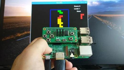
Constructing this Raspberry Pi retro video game controller is an enjoyable and relatively straightforward endeavor, albeit time-consuming.
Occasionally, waves of nostalgia sweep over me as I reminisce about the video games that filled my childhood days throughout the late ’80s and ’90s. While many of my old computers and gaming consoles have faded into the past, my trusty Raspberry Pi remains, offering a gateway to satisfy my yearning for retro gaming. I find solace in the straightforward games bundled with Raspbian, and the open-source RetroPie project has elevated my Raspberry Pi into a sophisticated retro gaming platform.
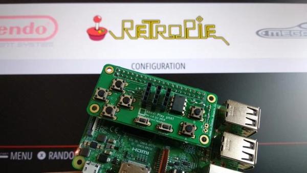
However, to truly immerse myself in the authentic gaming experience reminiscent of the “good old days,” I felt the need for a gamepad. While there are numerous options available on the market for USB gamepads and joysticks, my passion for open-source principles, coupled with my identity as a maker and engineer, drove me to pursue a more hands-on approach. Thus, I embarked on crafting my own simple open-source hardware gamepad, which I affectionately named the ANAVI Play pHAT. Designed as an add-on board for the Raspberry Pi, it incorporates an EEPROM and a devicetree binary overlay that I meticulously crafted for seamless key mapping.
There exists a vast array of gamepads on the market, with some boasting intricate designs. However, crafting a gamepad akin to the iconic NES controller using my design is surprisingly straightforward.
This gamepad comprises eight “momentary” buttons, which are switches that are active only while pressed. Specifically, it incorporates four tactile (tact) switches for directional movement (Up, Down, Left, Right), two tact buttons for A and B functions, and two smaller tact buttons designated for Select and Start commands. I opted for through-hole tact switches: six 6x6x4.3mm switches for movement and the A and B buttons, along with two 3x6x4.3mm switches for the Start and Select buttons.
While the gamepad primarily serves the purpose of retro gaming, the add-on board offers ample space to integrate home-automation features. These features may include monitoring temperature, humidity, light, or barometric pressure, providing utility even when gaming is not the focus. Additionally, I incorporated three slots for attaching I2C sensors to the primary I2C bus on physical pins 3 and 5.
A critical component of the hardware design is the EEPROM (electrically erasable programmable read-only memory). Employing a through-hole mounted EEPROM simplifies the flashing process on a breadboard and facilitates soldering onto the gamepad. An article in the MagPi magazine recommends the CAT24C32 EEPROM; however, if this model is unavailable, seek out a model with similar technical specifications. Notably, all Raspberry Pi models and versions released post-2014 (including Raspberry Pi B+ and newer iterations) feature a secondary I2C bus on physical pins 27 and 28.
Once equipped with this hardware setup, it’s advisable to utilize a breadboard for preliminary testing to ensure functionality.
Create the printed circuit board
The subsequent stage involves crafting a printed circuit board (PCB) design and arranging for its fabrication. As an advocate for open-source principles, I firmly believe in utilizing free and open-source software for creating open-source hardware. For this purpose, I rely on KiCad, an electronic design automation (EDA) software available under the GPLv3+ license. KiCad is compatible with Windows, MacOS, and GNU/Linux platforms, and personally, I use KiCad version 5 on Ubuntu 18.04.
KiCad offers the capability to design PCBs with up to 32 copper layers alongside 14 fixed-purpose technical layers. Additionally, it features an integrated 3D viewer. Continuously developed, KiCad benefits from numerous contributions by CERN developers and finds application in various industrial settings. For instance, Olimex utilizes KiCad to design intricate PCBs with multiple layers, such as those found in its TERES-I DIY open-source hardware laptop.
The KiCad workflow encompasses three primary stages:
1. Designing the schematics within the schematic layout editor.
2. Defining the edge cuts, placing components, and routing tracks within the PCB layout editor.
3. Generating Gerber and drill files for manufacturing.
For individuals new to PCB design, it’s important to acknowledge the steep learning curve associated with this process. It is advisable to familiarize oneself with KiCad through the provided examples and user guides to gain proficiency in working with both the schematic and PCB layout editor. Alternatively, for a more streamlined approach, one can simply clone the ANAVI Play pHAT project from my GitHub repository.
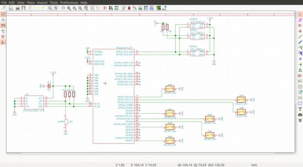
Within KiCad’s schematic layout editor, establish connections between the Raspberry Pi’s GPIOs and the buttons, link the slots for sensors to the primary I2C, and connect the EEPROM to the secondary I2C. Ensure each component is assigned an appropriate footprint. Conduct an electrical rule check, and if no errors are detected, generate the netlist, which outlines the electronic circuit’s connectivity.
Transition to the PCB layout editor, which encompasses various layers. Import and review the netlist. Ensure that all components and tracks are situated on the front and bottom copper layers (F.Cu and B.Cu), while the board’s outline must be delineated on the Edge.Cuts layer. Position any textual elements, including button labels, on the silkscreen layers.
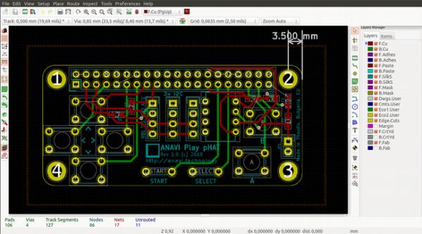
Lastly, export the Gerber and drill files, which you’ll forward to the company tasked with manufacturing your PCB. The Gerber format stands as the industry’s standard for PCBs. It operates as an open ASCII vector format for 2D binary images, akin to a PDF for PCB manufacturing.
Numerous companies specialize in producing simple two-layer boards like the gamepad’s. For a few prototypes, reliable options include OSHPark in the US or Aisler in Europe. Additionally, there is a plethora of Chinese manufacturers such as JLCPCB, PCBWay, ALLPCB, Seeed Studio, and many others. Alternatively, if you prefer to streamline the process of PCB manufacturing and component sourcing, consider ordering the ANAVI Play pHAT maker kit from Crowd Supply, allowing you to solder all the through-hole components yourself.
Understanding devicetree
Devicetree serves as a specification for a software data structure that delineates hardware components. Its primary aim is to enable the compiled Linux kernel to manage a diverse array of hardware configurations within a broader architecture family. The bootloader loads the devicetree into memory and subsequently transfers it to the Linux kernel.
Comprising three integral components:
- Devicetree source (DTS)
- Devicetree blob (DTB) and overlay (DTBO)
- Devicetree compiler (DTC)
The DTC transforms textual sources into binaries. Devicetree overlays facilitate the overlaying of a central DTB onto the devicetree, incorporating numerous fragments.
For several years, the integration of a devicetree has been mandatory for all new ARM systems on a chip (SoCs), encompassing Broadcom SoCs featured in all Raspberry Pi models and versions. In Raspberry Pi’s widely used Raspbian distribution, the default bootloader permits DTO configuration via the configuration file (config.txt) located on the FAT partition of a bootable microSD card, using the keyword device_tree=.
Since 2014, the Raspberry Pi’s pin header has been expanded to encompass 40 pins, with pins 27 and 28 designated for a secondary I2C bus. This enables automatic loading of the DTBO from an EEPROM connected to these pins. Moreover, additional system information can be stored in the EEPROM, in compliance with the Raspberry Pi Foundation’s prerequisites for any Raspberry Pi HAT (hardware attached on top) add-on board. On Raspbian and other GNU/Linux distributions for Raspberry Pi, users can access information from the EEPROM in userspace at /proc/device-tree/hat/ post-boot.
In my perspective, devicetree stands out as one of the most captivating features introduced in the Linux ecosystem in the past decade. While creating devicetree blobs and overlays constitutes an advanced task necessitating foundational knowledge, it is feasible to generate a devicetree binary overlay for the Raspberry Pi add-on board and flash it onto an appropriate EEPROM. The device binary overlay defines Linux key codes for each key of the gamepad, resulting in a gamepad for Raspberry Pi with keys functioning seamlessly upon booting Raspbian.
Creating the DTBO
Creating a devicetree binary overlay for the gamepad involves three primary steps:
1. Formulating the devicetree source with key mapping based on Linux key codes.
2. Compiling the devicetree binary overlay using devicetree compiler.
3. Generating an .eep file and flashing it onto an EEPROM utilizing open-source tools provided by the Raspberry Pi Foundation.
Linux key codes are defined in the file /usr/include/linux/input-event-codes.h. The device source file should delineate the mapping of Raspberry Pi GPIO pins to hardware buttons and the corresponding Linux key code triggered upon button press. For instance, in this gamepad configuration, GPIO17 (pin 11) links to the tactile button for Right, GPIO4 (pin 7) to Left, GPIO22 (pin 15) to Up, GPIO27 (pin 13) to Down, GPIO5 (pin 29) to Start, GPIO6 (pin 31) to Select, GPIO19 (pin 35) to A, and GPIO26 (pin 37) to B.
It’s important to note the disparity between GPIO numbers and the physical pin positions on the header. For convenience, all pins are situated on the second row of the Raspberry Pi’s 40-pin header, facilitating easier routing of the printed circuit board in KiCad.
The complete devicetree source for the gamepad is accessible on GitHub. As an illustration, the following excerpt demonstrates how GPIO17, corresponding to physical pin 11 on the Raspberry Pi, is mapped to the tact button for Right:
“`devicetree
button@17 {
label = “right”;
linux,code = <106>;
gpios = <&gpio 17 1>;
};
“`
To compile the DTS directly on the Raspberry Pi, install the devicetree compiler on Raspbian via the terminal:
“`bash
sudo apt-get update
sudo apt-get install device-tree-compiler
“`
Execute DTC and specify the output DTBO name and source file path as arguments. For instance:
“`bash
dtc -I dts -O dtb -o anavi-play-phat.dtbo anavi-play-phat.dts
“`
The Raspberry Pi Foundation provides a GitHub repository containing mechanical, hardware, and software specifications for HATs, alongside three useful tools:
– eepmake: Generates an .eep file from a text file with settings.
– eepdump: Facilitates debugging by dumping a binary .eep file as human-readable text.
– eepflash: Writes or reads an .eep binary image to/from an EEPROM.
Utilize the eeprom_settings.txt file as a template. While the Raspberry Pi Foundation and MagPi magazine offer valuable articles and tutorials, it’s advisable to consult them for additional details. The recommended EEPROM is CAT24C32, although it can be substituted with any other EEPROM possessing similar technical specifications. Using an EEPROM with an eight-pin, through-hole, dual in-line (DIP) package simplifies flashing for hobbyists as it can be executed with a breadboard. The following command example generates a file ready for EEPROM flashing using the eepmake tool from the Raspberry Pi GitHub repository:
“`bash
./eepmake settings.txt settings.eep anavi-play-phat.dtbo
“`
Before proceeding with flashing, ensure the EEPROM is correctly connected to the primary I2C bus (pins 3 and 5) on the Raspberry Pi. Then, execute the following command and adhere to the on-screen instructions to flash the .eep file onto the EEPROM:
“`bash
sudo ./eepflash.sh -w -f=settings.eep -t=24c32
“`
Before soldering the EEPROM onto the printed circuit board, relocate it to the secondary I2C bus on the breadboard for testing to ensure it functions as anticipated. If any issues arise during the breadboard testing of the EEPROM, rectify the settings files, relocate it to the primary I2C bus, and reflash as needed.
Testing the gamepad
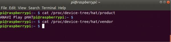
Now, onto the exciting phase! It’s time to put the add-on board to the test using Raspbian, readily available for download from RaspberryPi.org. Upon booting, launch a terminal and input the following commands:
“`bash
cat /proc/device-tree/hat/product
cat /proc/device-tree/hat/vendor
“`
The output should resemble the following:
Retro gaming with RetroPie
Raspbian certainly has its merits, but for avid retro gaming enthusiasts, RetroPie offers an unparalleled experience. It’s a specialized GNU/Linux distribution meticulously crafted for retro gaming, seamlessly integrating the renowned open-source projects RetroArch and Emulation Station. Compatible with Raspberry Pi, Odroid C1/C2, as well as personal computers running Debian or Ubuntu, RetroPie boasts a plethora of emulators designed for loading ROMs—the digital counterparts of classic game cartridges. It’s worth noting that RetroPie does not include any ROMs due to copyright regulations, so users must source and transfer suitable ROMs to their Raspberry Pi post-boot.
While the open-source hardware gamepad functions smoothly within RetroPie’s menus, I encountered a setback where the keys ceased to function properly upon launching certain games and emulators. After thorough debugging, I devised a solution to ensure their seamless operation within game emulators: incorporating a Python script for additional software emulation of the keys. You can find the script readily available on GitHub. Here’s a simple guide on how to acquire it and install Python on RetroPie:
“`bash
sudo apt-get update
sudo apt-get install -y python-pip
sudo pip install evdev
cd ~
git clone https://github.com/AnaviTechnology/anavi-examples.git
“`
To streamline the process, append the following line to /etc/rc.local to ensure automatic execution upon RetroPie boot:
“`bash
sudo python /home/pi/anavi-examples/anavi-play-phat/anavi-play-gamepad.py &
“`
Voila! By following these steps, you can assemble a fully open-source hardware gamepad as an add-on board for any Raspberry Pi model equipped with a 40-pin header, seamlessly compatible with both Raspbian and RetroPie environments.
Follow this link for complete project: Build Your Own Raspberry Pi Gamepad