The widespread of low cost embedded electronics makes it easier to implement the smart devices that can understand either the environment or the user behaviors [3]. The main object of this project is to design and implement home use portable smart electronics, including the portable monitoring device for home and office security and the portable 3D mouse for convenient use. Both devices in this project use the MPU6050 which contains a 3 axis accelerometer and a 3 axis gyroscope to sense the inertial motion of the door or the human hands movement.
For the portable monitoring device for home and office security, MPU6050 is used to sense the door (either home front door or cabinet door) movement through the gyroscope, and Raspberry Pi is then used to process the data it receives from MPU6050, if the data value exceeds the preset threshold, Raspberry Pi would control the USB Webcam to take a picture and then send out an alert email with the picture to the user. The advantage of this device is that it is a small size portable stand-alone device with its own power source, it is easy to implement, really cheap for residential use, and energy efficient with instantaneous alert.
For the 3D mouse, the MPU6050 would use both the accelerometer and gyroscope to sense user hands movement, the data are processed by MSP430G2553 through a digital smooth filter and a complementary filter, and then the filtered data will pass to the personal computer through the serial COM port. By applying the cursor movement equation in the PC driver, this device can work great as a mouse with acceptable accuracy. Compared to the normal optical mouse we are using, this mouse does not need any working surface, with the use of the smooth and complementary filter, it has certain accuracy for normal use, and it is easy to be extended to a portable mouse as small as a finger ring.
Introduction
Recently, with the fast development of electronic devices and smart home technology, lots of smart devices have been developed for a wide range of applications including wearable devices for convenient use, security electronics considering home security, etc. [8] They are all well designed with the purpose of optimizing the old devices as well as providing a more comfortable life. For example, the surveillance system, it cannot detect whether things happened or not, thus it will have to take videos all the time and will need human resources to monitor in case something really happens [10], therefore, it consumes a lot of power and need additional human resources. In addition, the surveillance can only detect buildings, street, etc, for things as small as a file cabinet, it is totally no use. The other example is the most frequently used device, computer mouse. It significantly changes the experiences of us using the computers, brought us a lot of conveniences. However, it always needs a working surface and will cause the computer mouse fatigue after long time of using [17]. Because of all these weaknesses, some whole new smart devices are quite necessary to optimize them.
In this project, I proposed a portable door monitoring device for home and office security and 3D portable mouse for convenient use.
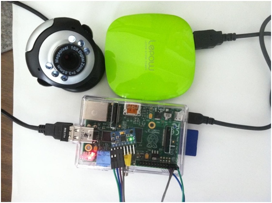
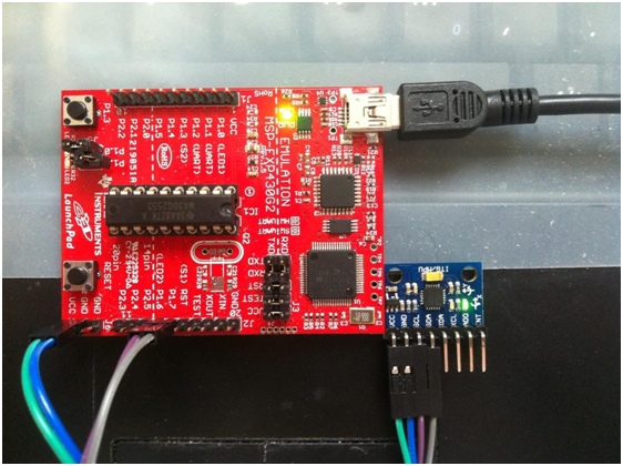
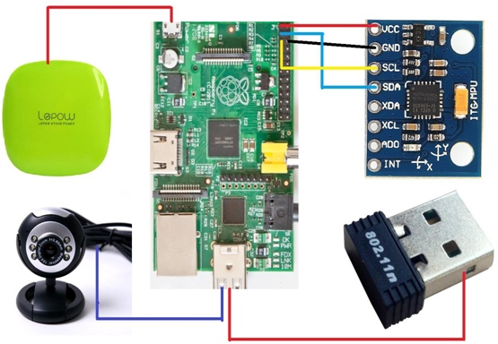
The door monitoring device is an event driven system, it will only take pictures or videos when things happened and send out alert email to the users for them to handle the break in immediately. The 3D mouse is using motion sensors to detect hand movement instead of optical sensors, so it does not need any working surface and will be more convenient to use. Both devices are using the MPU6050 to detect motion informations, either for doors or for human hand movement. Figure 1 shows the two system diagram of the two devices. A lot of experiments have been done to determine the threshold value and the hand movement function. Details will provided in the following section.
Part 1 Portable monitoring device for home and office security
1 Introduction
Burglary and theft have always been a headache for ordinary residents, especially for those living in the big cities. According to a report of Crime in the United States 2012, there are in total 2,103,787 burglaries happened across the whole nation. The average loss per burglary is 1675 US dollars. Thus it is quite necessary to find an effective way to significantly reduce it. Surveillance system has always been playing an important role in dealing with the burglary cases. However, it is expensive for ordinary residents to install such kind of system and it is also suffered the defect of not instantaneous, which means it does not inform the user immediately when the burglary happens [14]. What is normally the case is that we can only check the surveillance video after the burglary happened. Furthermore, because of the fact that surveillance systems record all the videos of everyday life, it has to be always in the working mode to record the videos, thus, it is a big waste of the electricity energy. On the other hand, the videos recorded by the surveillance system are in really low definition, sometimes even not clear enough to recognize the theft’s face. That is just because if the video is in high quality, the system would be more expensive and there would be not enough space to store all the video records [11]. Just because all of those weak points of the surveillance system, an energy efficient portable system that can take pictures or videos when the burglary happens and send out an alert signal at the same time is much better than the currently in use surveillance systems. In this project, a portable monitoring device for home and office security is proposed. This device is monitoring through an inertial motion sensor and also a webcam. Instead of taking videos all the time, this device will only take a picture or video through the webcam when something bad happens, thus it significantly reduces a lot of power. In addition, it also has an embedded Linux email server to send out an alert email when burglary or theft happens. Compared to that of the surveillance system, this device is totally portable with its portable external battery; it has really small size that can be placed on any kind of doors, for example, house front door, cabinet door, etc; it is also really cheap that is good for normal residential use. The device is composed of MPU6050, webcam and Raspberry Pi. The MPU6050 is a 3-axis accelerometer and 3-axis gyroscope, the gyroscope is used to detect the movement of the door. The webcam is a normal 640 * 480 resolution camera to take a picture of the theft that breaks in through the door. The Raspberry Pi is an embedded Linux computer to do data processing and send out alert email to the user when a break in occurs. The whole system is a stand-alone device with its own power source.
2 Methodology
For a device to be used as an effective portable monitoring and alert system, it has to have at least three functions, which are detection, picture taking and alert mechanism [13]. Then first, how can we decide whether someone has been breaking in? According to the data on asecurelif.com, 34% of the burglars enter through the front door and the master bedroom is almost always the first room targeted. Thus if we can detect the movement of the residents’ front door or bedroom door, a break in can be easily noticed. Then a movement sensor is needed here. Accelerometer and gyroscope are both good choices. However, if we think deeper about the movement of the door, it is very clear that the door is rotating around the fixed axis, so angular velocity will have a more regular pattern than the acceleration data. Thus, the 3-axis gyroscope in the MPU6050 is used to detect the door movement. After the movement signal is detected, the device need to take a photo of the burglar and sent out an alert signal to the user. A webcam is controlled by Raspberry Pi to take the picture. Finally, what kind of alert information and how can the information be sent out? Text message and email are both really good choices, because text message will need GSM module and SIM card [10], so email is chosen as the alert signal. Normal microcontrollers can control the MPU6050, but they cannot send out alert emails, even with Wi-Fi module, normal microcontrollers will still need a PC as an email server, which is not a stand-alone system. Therefore, in order to both control the sensor and sent out alert email, embedded Linux would be a really good choice. Thus, Raspberry Pi is chosen as the controller of MPU6050 and also a SMTP email server.
The whole device works in this way, the Raspberry Pi will control the MPU6050 through the I2C bus. When the gyroscope normalized movement signal is detected, Pi will control the webcam to take a picture and send out an alert email along with the photo to the user so that they can handle the emergency immediately.
3 System architecture
The whole system is composed of five parts, the Raspberry Pi embedded Linux controller, the MPU6050 sensor, the Wi-Fi adapter, the webcam and the power supply. Figure 2 shows all the components of the whole system.
1.1 Raspberry Pi
- Raspberry Pi Introduction
Raspberry Pi is a single board computer with Linux or other small operating systems. It was developed in UK by Raspberry Pi foundation for computer science education use. (wiki-pedia)
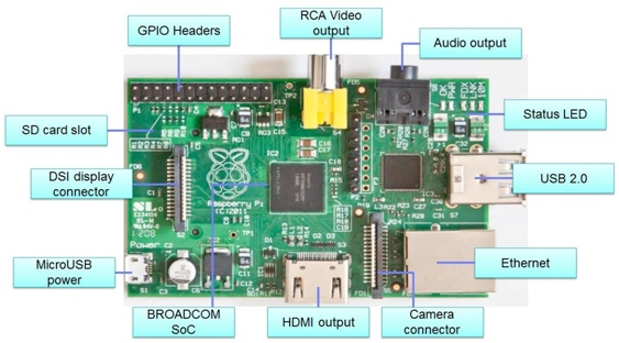
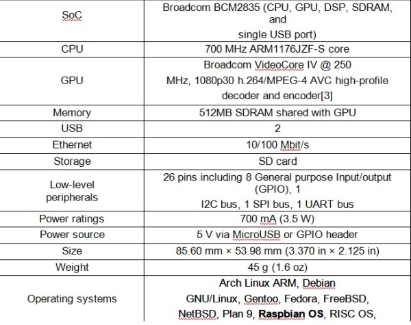
The one used in this project is the second version of it. It has an ARM 1176JZF-S processor, which runs at 700MHz clock speed, a VideoCore IV GPU, 512MB SDRAM shared with GPU, 2 USB port, 1 video and audio output, 1 100 Mbit/s Ethernet port, 1 HDMI output. It also has 26 pins including 8 General purpose Input/output (GPIO), 1 I2C bus, 1 SPI bus, 1 UART bus and 3.3V, 5V and GND. Figure 3 shows the full view of Raspberry Pi. Thus it can be used as a really powerful microcontroller which can fulfill almost any functions, and in the meantime, acting as a normal use computer with keyboard, mouse and monitor connected. Table 1 shows detailed specifications of Pi.
Raspberry Pi does not have on chip memory, so it needs an external SD card to store either its operating system or all the user data. Raspberry Pi can be used in both ways, either connect to keyboard, mouse and monitor be used as a normal computer or connect it to the local network so that it can be controlled through SSH terminal. All the specifications would be discussed in the next section.
- Installing an operating system
The system used in this project is Raspbian OS that raspberry foundation supplied. In order to install the operating system, first go to the Raspberry Pi official website and download the latest system image, then use the win32disk imager to write the image into your SD card using your personal computer. Finally if everything goes well, plug the SD card into Pi and the system is good to go. If the status led successfully blink, then the system is installed properly. First time start up might take a little while, but after that the system will be running really fast.
- Control Raspberry Pi
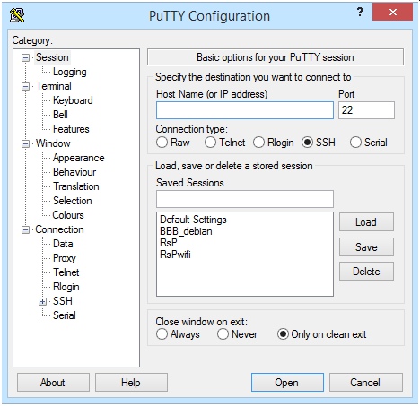
In this project, the Pi is used as a totally stand-alone system, so keyboard, mouse and monitor are all not necessary. The Pi will be controlled by using its IP address through the SSH terminal. There are a lot of SSH terminal can be used, Putty is chosen in this project. In addition, eclipse is using to do data transfer between my computer and Pi. This data is the testing programs I wrote in my PC. As I said, the Pi is controlled through its IP address, so internet cable must be plug into the Ethernet port, or a Wi-Fi adapter plug in the USB port. If Pi is in a local network, the IP address can be found by accessing the router, otherwise, a specific software is needed to get the actual IP address of Pi. Figure 4 shows the GUI interface of Putty where you can type in the IP address and access Pi. After access into Pi, user name and password would be needed, in this case, the default user name is pi and the password is raspberry. Figure 5 shows the interface after we access Pi successfully.
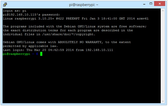
After accessing into Pi successfully, we can use the Linux system in command-line interface. Some basic Linux commands will be introduced in the next session.
- Linux command introduction
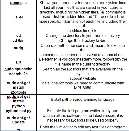
Table 2 shows some basic Linux command used in the project. A lot of different tools are used in this project, including i2c-tools for basic i2c communication, python-smbus for doing i2c in python environment, python-opencv for taking picture using the webcam and ssmtp for sending email using the smtp server. The test program is programmed using python language.
3.2 MPU6050
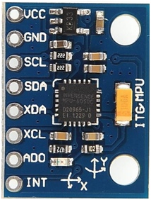
MPU6050 is the world’s first integrated 6 axis motion sensor, it combines one 3 axis accelerometer and one 3 axis gyroscope, and it has its own digital motion processor (DMP) which can process the motion data with its inside algorithm [2]. It can output 6 axis raw data as well as 6 axis data which pass through the Kalman filter or processed by the Quaternion algorithm. However, access to the filtered data as well as the DMP need specific permission, so only the raw data is used in this project. This sensor can also attach a 3 axis compass through the I2C bus which makes it a 9 axis inertial motion sensor. The chip itself has an internal 16 bit analog to digital converter (ADC), so the output data are 16 bit digital values [2]. There are 117 registers in total inside the chip and all of the registers are 8 bit, so it needs two registers to hold the value for one axis’ data. The detection range of the accelerometer is +2g, 4g, 8g,16g and that of the gyroscope is +250, 500, 1000, 2000º/s, the range can be chosen by setting the corresponding registers. MPU6050 is communicated with Raspberry Pi through the I2C data bus at the clock frequency of 100 kHz. Figure 6 shows the break out board of MPU6050.
The output value of the chip is not the actual acceleration or angular velocity. It has to be calibrated according to the calibration value in the datasheet. For example, if the range of the accelerometer is ±4g (or
±500 for the gyroscope) according to the datasheet, its units is 8192 LSB/g (65.5 LSB/ (°/sec ) for the gyroscope), which means that if the digital data we get from the chip is 9000, the actual value should be 9000/8192=1.1g for the accelerometer and 9000/65.5=137.4°/sec for the gyroscope.
3.3 Webcam
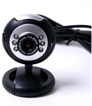
The Webcam used in the device is SANOXY USB 6 LED Night vision PC Webcam.
It is a high performance webcam and PNP(Plug and Play)product for real-time data transmission to PC via USB port. It has a high resolution and fast transmission rate. It uses a color CMOS image sensor with the resolution of 640×480, the video format is 24bit RGB and the videos it make have the specification of 320×240 up to 30frame/sec and 640×480 up to 15 frame/sec(VGA). The S/N ratio is 48dB and the dynamic range is 72dB. Its focus range is 3cm to infinity. It has built-in image compression and automatic white balance. The USB Cable Length is 1.3m. Figure 7 shows the picture of the camera.
3.3 Power supply
The power source used for the device is a 6000mAh external battery for smart phones and tablets. The size of this battery is 3.2 x 3.2 x 0.8 inches and it weighs 9.6 ounces. The input current for this battery is 5V/1000mA. And it has two output ports, one with the current of 5V/1200mA and the other is 5V/2100mA. The 5V/2100mA is just right choice for Raspberry Pi. Figure 8 shows the image of the external power source.

4 Results
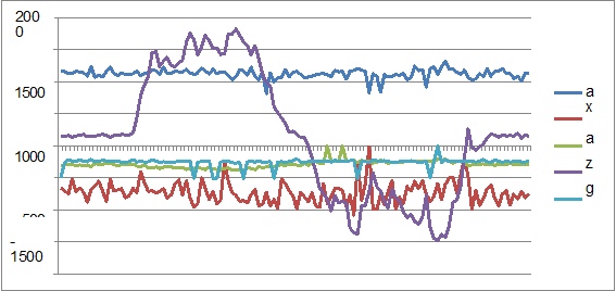
Lots of Experiments have been done to determine the threshold and the movement trends of different doors. Figure 9, 10 and 11 show the experimental data of moving the door slowly, normally and fast. The experiment condition is in this way, the y axis of the sensor is parallel to the direction of the gravitational force, so the value of that axis is around 16384 (equal to 1g) and that’s why I didn’t show it in the diagram. Because of that, the door is rotating around the y axis of the sensor. From the figure, we can found out these different characteristics. First, the accelerometer does have some values, and the amplitude of the value is bigger along with the movement, but it does not have a clear pattern like that of the gyroscope, so it is not a good choice for determine the rotational movement. Second, the gyroscope x axis and z axis do not have any value, which makes sense because there is no rotational movement around that two axis. Third, the y axis of the gyroscope has a really clear pattern, it means that in the first two tests, the door is opened and closed for one time, but in the last test, the door is opened and closed twice. The gyroscope can determine the movement pattern really clearly.
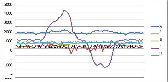
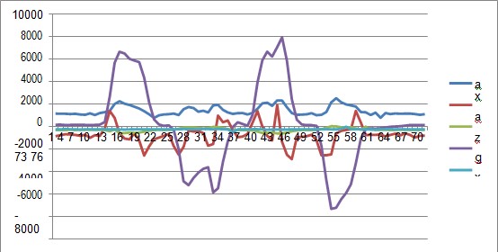
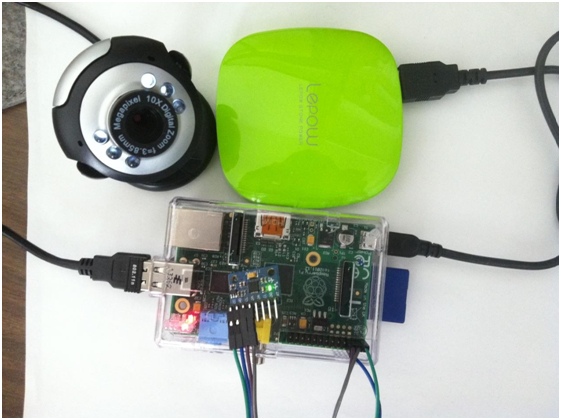
Forth, the amplitude of the y axis gyroscope value increases as the door movement speed increase. Thus there are two ways to detect the door movement, wither by monitoring the whole pattern of the door movement or by set a single threshold value. The second way is chosen in this project and the threshold value is 1500. It is not too high to miss the slow motion values but also not too low to detect unexpected motions. Furthermore, the y axis of MPU6050 is parallel to the direction of the gravitation in the experiment set, however in actual use, the device can be placed in any direction, thus the gyroscope data has to be normalized by equation 1. By implementing the whole device on the door or cabinet door, it can detect the motions and send out the alert email. Figure 12 shows the final setup of the device.
Source: DESIGN AND IMPLEMENTATION OF HOME USE PORTABLE SMART ELECTRONICS
