I. Summary
The IoT Smart Alarm Clock is an open-source project that enables users to create and customize their alarm clock leveraging the Internet of Things technology. This thorough project offers a step-by-step process for constructing the smart alarm clock, covering features such as text-to-speech capability, multiple wake-up sound selections, smartphone and computer control, Apache2 server integration, automatic brightness adjustment based on light, audio volume control, a 3D-printable enclosure, tactile switch, alphanumeric display, and a robust 3W speaker to ensure an effective wake-up notification.
II. Objectives
The main goal of this project is to facilitate the development of an Internet of Things (IoT) Smart Alarm Clock, giving students a hands-on learning experience to acquire and apply practical IoT device development skills and knowledge. Through building the smart alarm clock, students can gain first-hand experience in designing and implementing an IoT-enabled device.
III. Industry-Based Applications
Digital Logic Design represents the signals and sequences within digital circuits using numerical values. It underlies how computing and hardware exchange information internally. Virtually all electronics incorporate digital logic, whether in calculators, computers, video games, watches, and more. This project provides insights into interfacing IoT (Internet of Things) devices with circuits. Such skills relate to engineering careers that involve designing smart products. For example, engineers may develop smart lights, appliances for smart homes, televisions, phones, and other connected devices. Learning to integrate IoT capabilities allows students hands-on experience that could apply directly to jobs developing innovative smart technologies.
Iv. Project Methodology
A. Components
1. Raspberry Pi Zero (with minor changes, you might as well use a different Raspberry Pi)
- Keyboard, Mouse, and Screen (for initial setup)
- Micro SD Card (8 GB or more is recommended)
- USB-WiFi-Stick (for example: EDIMAX EW-7811UN Wireless USB Adapter)
- Audio Amplifier (PAM8403)
- Hole Grid Board (70mm x 50mm x 1.2mm, 24×18 holes, plus one hole in each corner, can be found easily online)
- Button (Tactile Switch)
- Photocell (Photoresistor)
2. Speaker (3 Watt, 4 Ohm 40mm diameter)
- 14-Segment Alphanumeric Display
- Screws: 4x M2 6mm, 4x M2.5 6mm, 4x M2.5 16mm
- Resistors, Capacitors, and wires
- Procedure
a. Raspberry Pi Zero Running Raspbian
i. To complete this project, you must set up a Raspberry Pi with the Raspbian (Lite) operating system, which is the Debian version adapted for Raspberry Pi. Of course, you can experiment with different boards and operating systems if desired, but some adjustments may then be required. For example, if using a Raspberry Pi 3 instead, you could leverage its built-in WiFi without an additional WiFi dongle, and potentially use the onboard audio jack rather than an external one. However, it may not perfectly fit inside the provided 3D-printed casing. And keep in mind, these instructions are tailored for the Raspberry Pi Zero model. So substituting certain components would necessitate modifying the steps accordingly.
Installing Raspbian
ii. To start, visit the Raspberry Pi downloads page and obtain the most recent version of the Raspbian Lite image file. Since this project does not need a graphical user interface, we chose the lighter Raspbian Lite variant. Next, follow the directions on the download and media setup page to copy the Raspbian image onto your SD card. Once the SD card preparation is finished, insert it into your Raspberry Pi device. Then connect a mouse, keyboard, and monitor to your Raspberry Pi to interface with it.
Enabling SSH (Optional)
iii. If students want to control their Pi via remote, access the Raspberry Pi’s configuration menu and activate the SSH feature.
sudo raspi-config
iv. Select the Advanced Options menu and press Enter. Then enable SSH by highlighting and selecting the corresponding option. Once SSH is enabled, restart your Pi by running the command ‘sudo reboot’. This will cause the changes to take effect. Specifically, you can enable SSH by running:
ifconfig
v. After the booting of Raspberry Pi board, the IP address of the board will appear on the monitor that is connected. If you have joined both the Pi and your computer to the network space then you are capable of using SSH from your computer to Pi. For example, you would use a command like:
ssh pi@ip-address
vi. Enter the password and log in to your Pi.
b. Display
i. This stage involves soldering and configuring the “Alphanumeric Display”.
You have the option to use a different display than the one specified in this guide. If you choose an alternate display, you may need to modify some aspects of the code and 3D-printed enclosure design. We are using the “Adafruit 0.54” Quad Alphanumeric FeatherWing Display supplied by Adafruit. This features a 14-segment Alphanumeric LED FeatherWing with an HT16K33 driver chip that allows for multiplexing commands to control the display. This enables control of the display from the Raspberry Pi using the I2C protocol. Additionally, Adafruit provides a readily available library that lets us conveniently send various strings to the display. However, before utilizing the library, we will first attend to the soldering process required to install the display.
Display Assembly
ii. Refer to the assembly directions from Adafruit for installing the display and Feather wing board. To begin, solder the required pin connections between the display and the Feather wing board.
iii. Once the pins are soldered to the Feather wing board, attach the display board. Solder each of the display’s pins to the corresponding points on the Feather wing board. While doing so, consult the Adafruit tutorial again for exact placement and orientation details to ensure proper assembly of the components.
iv. To test the display functionality, you will need to connect it to your Raspberry Pi. For the necessary wiring, take a set of multi-colored wires. We suggest first cutting an opening in the center of the 70mm x 50mm perforated board before assembling all the pieces. This board is intended to sit neatly within the provided enclosure. Use a cordless drill as shown in the accompanying photos to cut the hole in the board.
v. If you have already 3D printed the case enclosure, use this time to ensure everything fits properly together. Position the speaker inside the designated cut-out area and place the perforated board on top. Please note the hole placement of the four edge holes on the board may vary slightly depending on production quality differences. If two of the holes do not exactly align with the matching screw holes, that is not a problem. Once assembled, the components will still be securely held in position even with only two screws used for fastening.
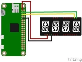
vi. Now that the perforated board is ready, the next step is to solder the display to the Raspberry Pi. Take your multicolored wires and cut them to roughly 10 cm in length. Align the display centrally within the top row of holes on the board. Reference Adafruit’s pinout diagram for exact wiring details. Connect four cables: 3.25 Volt, Ground, and the two I2C lines – SDA and SCL. Examine the close-up circuit image for guidance on how to link the display correctly to the Raspberry Pi.
vii. If you have successfully soldered and installed the display and Raspberry Pi onto the perforated board, your assembled setup should now match the final depicted diagram.
viii. The next step is to install the appropriate Adafruit library.
Install Display Library
ix. Now that the assembly is finished, the Adafruit_LED_Backpack library needs to be installed. Start by running the following command:
sudo apt-get update
sudo apt-get install build-essential python-dev
x. You will also need to install the python-smbus and python-imaging libraries. Run this command to install both:sudo apt-get install python-smbus python-imaging
xi. In your Raspberry Pis home folder, type:
git clone https://github.com/adafruit/Adafruit_Python_LED_Backpack.git
xii. To clone the Adafruit GitHub repository containing the library files onto your Raspberry Pi, follow these steps: First of all make a copy of the clone in the Pi using the command: Then extract the downloaded file. Next, change directories into the library’s folder and run the setup.py file to install it:
sudo python setup.py install
Testing the Display
xiii. Once the library installation has finished without issues and your assembly matches the diagram, you can test that the display is working properly. First, activate the I2C protocol by running:
sudo raspi-config
xiv. Navigate to the Advanced Options menu, enable I²C protocol, and reboot: sudo reboot.
xv. Update your Pi to apply the changes. Next, navigate to the folder by typing: cd /Adafruit_Python_LED_Backpack/examples/
xvi. and run the following test script:
python alphanum4_test.py
xvii. If all the steps have been followed correctly up to this point, you should now be able to see text scrolling across the display. However, if not all segments are lighting up as expected, it would be worthwhile double-checking your solder joints to ensure a proper connection between all components. Verifying the soldering quality can help troubleshoot any issues with full display functionality.
c. Clone Project Code
i. Before physically testing the components in later steps, it’s recommended to obtain the code for the Smart Alarm project from its GitHub repository onto your Raspberry Pi. Make sure you have access to a terminal, either through SSH or by directly connecting a screen and keyboard. Initialize an internet connection and change to your home directory by typing cd. To download the source code repository, first install Git by running this command:
sudo apt-get install git
ii. Next type:
git clone https://github.com/fgebhart/smart_alarm.git
iii. Clone the repository files to your Pi. This process may take a few minutes. After all the files are downloaded, navigate to the folder /home/pi/smart_alarm/tests/ by typing:
cd /home/pi/smart_alarm/tests/
iv. Execute the following Python script to display the time on your alphanumeric display.
python display_time.py
v. Also, you might want to run
python scroll_text.py
vi. As a test, run the provided Python script. If you have difficulties with the Adafruit Python LED Backpack library, re-examine the directions in Section 2 – Display. Also, review the Adafruit 14-Segment Alpha-numeric LED FeatherWing tutorial to verify all assembly and installation steps were completed correctly. Checking these resources may help resolve any issues interacting with the display.
d. Step 4 Enable audio
4.1 Low-Pass-Filter Circuit
i.You may have noticed that the Raspberry Pi Zero does not have built-in audio capabilities, which could prevent the effective use of alarms for timely wake-ups when building a clock. Not to worry – the community has devised solutions for this restriction. To provide rudimentary audio functionality on the Raspberry Pi Zero, go through the Adafruit guide and select Option 2, Manual Assignment of PWM Pins. Outlined below is a brief overview of the required process. Begin by upgrading your Pi software:
sudo apt-get update
ii. Then install the GPIO library:
sudo apt-get install raspi-gpio
iii. Clone the WiringPi repository to your Pi and install it like described in this tutorial by typing:
git clone git://git.drogon.net/wiringPi
iv. Once it is successfully downloaded, change directory and build the files: cd ~/wiringPi
./build
v. Run:
gpio -v
vi. and
gpio readall
vii. Verify the success of your installation by checking the pin functions of your Raspberry Pi Zero, as depicted in the read-all output:
viii. Change directory to:
cd ~/smart_alarm/tests/
ix. Now compile and install the file gpio_alt.c by typing: gcc -o gpio_alt gpio_alt.c
sudo chown root:root gpio_alt sudo chmod u+s gpio_alt
sudo mv gpio_alt /usr/local/bin/
x. Finally, we will modify the alternate functions of the Raspberry Pi’s GPIO pins. As previously mentioned, we aim to change the functions of pins 13 and 18 to enable PWM. To achieve this, type:
gpio_alt -p 13 -f 0
gpio_alt -p 18 -f 5
xi. Note that the alternate functions will revert to their default state whenever you reboot your Pi. Don’t worry, we’ll address this by creating a script that runs on bootup. After running the command `gpio readall` again, you’ll notice the newly assigned functions for pins 13 and 18.
xii. By utilizing the alternate function of pins 13 and 18, we can enable pulse-width-modulation (PWM) and generate a basic audio output along with a small low-pass filter circuit. Please refer to the following schematic diagram for guidance on wiring the circuit.
xiii. Building the defined low-pass filter requires several resistors and capacitors. Rather than directly soldering the circuit onto the perforated board, we recommend first constructing it on a breadboard. This allows you to properly test the wiring configuration before final assembly. The schematic shows two low-pass filters, one for the right audio channel and one for the left. However, for this single-speaker project, only one audio output is needed. The following images still depict two filters due to earlier plans to include two speakers. But don’t worry about that – for your needs, a single low-pass filter connected to one speaker will be sufficient. Test out the circuit using the breadboard before finalizing the design.
The resistors required for the low-pass filter are 150 Ohm and 270 Ohm. The capacitors should ideally be 10 nF and 1 μF. See if you can find an open area on your perforated board where the resistors and capacitors won’t touch the back of the speaker, similar to how it’s shown in the next picture. Try positioning some resistors and capacitors, without connecting them yet, in the same layout as the rear of the speaker on your perforated board as depicted in the following image:
xiv. Solder the wires based on the Fritzing schematic diagram above. Once finished, your circuit should match the subsequent picture. Note the green wires at the bottom originating from Raspberry Pi Zero pins 13 and 18. The black wires at the top stem from the Pi and act as ground connections. The green wires along the edge of the board carry the audio output signal from the low-pass filter, which will then be transmitted to the speaker and eventually amplified by the amplifier module to increase the volume level.
xv. Please note again that you only need a single low-pass filter, as you are only connecting one speaker which only requires one filtered audio output signal. You do not need to construct both of the filters shown in the diagram.
Testing Sound
xvi. Once you have completed building the circuit and configured the alternate pin functions using a device tree overlay as detailed in this guide, you can test the Raspberry Pi Zero’s sound playback capabilities. It may also help to install omxplayer by running the command [insert command here]. Note that if you used the full Raspbian OS image instead of the Lite version, omxplayer would already be pre-installed on your system.
sudo apt-get install omxplayer
xvii. now change the folder and run omxplayer to play the example audio file: cd ~/smart_alarm/tests/
omxplayer example.mp3
Install pygame
xviii. In addition, you must install the Pygame Python library to be able to play audio files via your Python script. To get Pygame, you will need to:
sudo apt-get install python-pygame
xix. Once Pygame has finished installing, you will be able to test it by running the following command:
xx. python smart_alarm/tests/play_sound.py The play_sound.py script reads the file in
/home/pi/smart_alarm/smart_alarm/music/Festival.mp3 and uses pygame library to play the .mp3 file.
Install Python Text to Speech
xxi. In addition to playing .mp3 audio files, we want our alarm clock to have the capability of spoken words/announcements. To enable text-to-speech functionality, we need to install the Python pyttsx package. First though, we need to install pip, the package management system used to install Python packages.
sudo apt-get install python-pip
xxii. Now install pyttsx and the necessary python-espeak library: sudo pip install pyttsx
sudo apt-get install python-espeak
xxiii. Again, test your system by running:
python smart_alarm/tests/say_text.py
xxiv. This script prompts you to enter a text and reads it by using pyttsx and espeak.
Install Music Player Client & Daemon
xxv. To truly maximize the capabilities of our IoT alarm clock, we will install the Music Player Client and Daemon. This will grant the ability to access a wide variety of internet radio stations using the mpc client utility. Streaming radio is an important element to deliver an engaging experience, as intended for this project. Therefore, let us begin the installation steps required to support Internet radio functionality.
sudo apt-get install mpd mpc
xxvi. Now you can use your client to play the internet radio station you like. Check the most important commands:
xxvii. mpc add radio_station_name : Adds your station to the mpc playlist
xxviii. mpc playlist : Displays the content of the mpc playlist
xxix. mpc clear : Clears the current playlist
xxx. mpc play : plays your playlist with one radio station at random
xxxi. mpc stop : stops the play of some station
xxxii. Ultimately, we run those commands through our Python scripts using the OS library within Python, as illustrated below.
os.system(‘mpc play’)
xxxiii. But before we can start playing your personalized radio stations, we first need to add at least one station to your playlist. With millions of options out there, you’ll surely find one you love. To save you time and effort, I recommend using one of the two options below:
xxxiv. http://streaming.radionomy.com/The-Smooth-Lounge?l…
xxxv. http://orange-01.live.sil.at:8000
xxxvi. Interestingly, due to regional differences, some stations may include commercials. This isn’t a concern for our system, though! To add the desired internet radio station to your playlist, simply enter the following command in the command line of your Raspberry Pi Zero:
mpc add http://orange-01.live.sil.at:8000
xxxvii. Now start and stop your playlist in order to check if the music player client is working.
e. Audio Amplifier
i.This section will address boosting the system volume level. To help prevent accidental oversleeping and deliver suitable volume output, we suggest employing an audio amplifier. This will strengthen the audio capabilities of the project and enable it to perform similarly to a compact music player. For this purpose, we’ve selected the affordable and straightforward-to-implement Stereo Audio Amplifier PAM8403 chip, according to its published specifications.
Connecting the Amplifier
ii. Consider the following fritzing schematic for wiring information:
iii. As we outlined earlier, another Raspberry Pi pin is being used to control the amplifier module. Specifically, the yellow wire connected to GPIO 12 is linked to the amplifier’s switch input. Therefore, any Python scripts going forward will need an additional code line (not to worry, we provide the necessary code) to activate the amplifier by sending a logical ‘1’ to turn it on and ‘0’ to turn it off. This is helpful as it avoids unwanted noise from the Raspberry Pi’s pulse-width modulation functionality. Once all the connections are made, your completed configuration should match the diagram shown below.
Testing the Amplifier
iv. Again run one of the following command in order to test the volume of your system: omxplayer ~/smart_alarm/test/example.mp3
python ~/smart_alarm/test/play_sound.py python ~/smart_alarm/test/say_text.py
v. Since the sound is now significantly louder, it’s a good idea to adjust the system volume of the Raspberry Pi as well. To do this, simply type:
amixer set PCM — 100%
vi. Specifically, this command adjusts the system volume to its maximum level (100%). If you’re struggling to play sounds, it’s possible that the GPIO pins’ alternate functions are still active. After rebooting your system, the default function will take over, preventing PWM sound playback on your Pi Zero. To regain audio functionality, revisit Section 4: Enable Audio. More likely than not, you’ll need to re-enter the following commands:
gpio_alt -p 13 -f 0
gpio_alt -p 18 -f 5
vii. This command will eventually be incorporated into our autostart script. It appears we’ve completed our exploration of playing sounds. What’s the next step? Why, stopping the sounds, of course!
f. Button
i. Ending the alarm sounds with ease – just incorporate a button. Now that you’re alert, it’s time to silence the alarm. To support this, we’ll develop a stop mechanism for our project beginning with integrating a button.
Connecting the Button
ii. Such as with the use of bouncing and debouncing, users who are already well initiated with the buttons may already be aware of these terms. To the ones unfamiliar with this case, I point out to this great guide made by Raspi. TV to gain adequate knowledge in this regard. However, if you feel that you want to get right to the heart of the matter, go for it; take your button and begin wiring. For a visual reference, take a look at the following Fritzing diagram:For a visual reference, take a look at the following Fritzing diagram:
iii. Regarding the wiring, you should economize on the space at the lowest part of your PCB and join the connections to the speaker. Do not move too near to the actual speaker on the shaft. Assembling of the circuit requires two resistors – one kilo-ohm (1k) and 10 kilo-ohm (10k) and one one-hundred nano farads (100nF capacitor) and wires. Connect all the items in a proper way following the aforementioned diagram. Precisely, join the 1k Ohm resistor across the two wires of red color and 10k Ohm resistor between the wire of yellow and black color. Your finished soldering on the PCB should look like this: The front side should look like this:The front side should look like this:
iv. And on the back:
v. Greetings, if you have the case printed and would like to share the schema for the button’s position or should anyone need it – here it is!
Testing the Button
vi. Similarly to the previous steps, we will use the Python testing script situated in the project repository. Assuming your button is properly connected as outlined earlier and you’ve cloned our repository, execute the provided Python script: Assuming your button is properly connected as outlined earlier and you’ve cloned our repository, execute the provided Python script:
python smart_alarm/tests/button_input.py
vii. Look for “button is: 0” repeatedly appearing in your terminal. Upon pressing your button, the line should update to read “button is: 1”. If you’re seeing this, awesome – your soldering is correct! If not, revisit the Fritzing diagram from earlier and review the tutorial for any mistakes.
g. Photocell
I. The next Fritzing schematic shows you how to connect your photocell to the setup, so ensure to pay attention to this. Just to remind yourself; this diagram means the entire integrated, completely constructed wiring diagram, for the Smart Alarm project.
ii. Notwithstanding, since the photocell and button consume miniscant power, it is reasonable to connect both the power supply pin & ground pin to the Raspberry Pi Zero board. In this regard, ensure that the photocell wires are connected to the solder joint at the next side of the button at the bottom external edge of the hole grid board. Your connections should resemble the following: Your connections should resemble the following:
iii. It is pertinent to state that photocell should be placed at the top of the case and use 15cm long wires for this purpose. If the photocell does not fit in the designated hole properly, you can attempt to make the opening a little bigger with a knife. Next, it is advisable to use a pin or thin tool to press the photocell into the flatlay case firmly. Pass the wires through the slit cavity cut towards the interior wall between the top and the main body of the case. Your final installation and wiring should resemble the image below: Your final installation and wiring should resemble the image below:
h. Testing the Photocell
i. After you connect your photocell in the way that you are satisfied with, it is advisable to check it. Therefore navigate to the /tests folder and run the following Python script by typing: $ cd ~/smart_alarm/tests/
python reading_brightness. py
ii. Ideally, if you have done all the steps correctly, this script should print out the ambient brightness levels in the output console. As a confirmation, try putting your fingers on the sensor and watch the results in the terminal.
i. Setup Apache Server
i. Simplifying the clock’s design was a key part of our process. To achieve a clean, straightforward interface, we wanted a configuration method that relied on only a single button. As such, we implemented a web-based solution utilizing an Apache server on the Raspberry Pi. This allows users to set the alarm time, choose content to play, and adjust other settings – all without adding extra buttons or complexity to the physical clock. The web interface ensures easy configuration while maintaining our focus on a minimalistic design.
Installation of Apache Server
ii. Follow these steps to install the Apache web server on the Raspberry Pi Zero:
sudo apt-get install apache2 -y
iii. Due the fact that we are using python scripts on the server, it is necessary to install the wsgi module for apache:
sudo apt-get install libapache2-mod-wsgi
iv. Usually the module gets automatically enabled if installed, if not, please run the following line:
sudo a2enmod wsgi
v. Further Information about the wsgi module can be found here.
Configuration of the Apache server
vi. The next step is to configure the Apache server. Since Apache does not have access to the system’s environment variables by default, we need to explicitly declare them. To do so, add the following lines to the bottom of the /etc/apache2/envars file:
Set smart alarm path variables
export smart_alarm_path=/home/pi/smart_alarm/smart_alarm
vii. An example of what the file should look like can be found in the git repository under smart_alarm/misc/apache.
viii. After that, we can use the variable in the apache config files. The goal is, that our python_server.py script is getting executed when the server is called in a web browser. The easiest way to achieve this is to replace /etc/apache2/sites-available/000- default.conf with our 000-default.conf under smart_alarm/misc/apache:
sudo cp smart_alarm/misc/apache/000-defaul.conf/etc/apache2/sites-available
ix. Essentially, this links the server’s root directory “/” to the Python script, and gives the Apache server read access to this folder. The last step is granting Apache write permissions for the data.xml file. Apache typically runs as the “www-data” user. There are a few different methods for giving www-data write access to this file. The simplest approach, though not necessarily the most secure, is to open write permissions for all users. This can be done by changing permissions in the file’s folder:
/smart_alarm/smart_alarm/with following lines: sudo chmod o+w data.xml
Testing of the Apache server
x. After that, you should see the following webpage if you call the ip address or hostname of the raspberry pi in a web browser.
xi. On a PC:
xii. On a mobile phone:
j. Configure Setup
i. This section outlines the remaining configurations needed to complete the setup. We’ll cover system configuration, and linking the autostart.sh script to automatically run on boot, modifying the Pi’s hostname for more convenient access, and changing the default user password for enhanced security. Making these final changes will fully prepare the system to run as intended on startup with improved usability and protection.
Autostart Script & Environment Variable
ii. Since several components need to reference the path containing the Python scripts, we will define an environmental variable to hold this location. The preferred method is to add environment variables to the /etc/environment file. To define the “smart_alarm_path” variable, insert the following line at the end of /etc/environment:
smart_alarm_path=”/path/to/smart_alarm/smart_alarm”
iii. By default, the path would be “/home/pi/smart_alarm/smart_alarm”. In addition to Apache, which should remain running continuously, the smart_alarm script also needs to launch automatically on system startup. To accomplish this, add the following two lines before the “exit 0” in /etc/rc.local. This will cause autostart.sh to execute automatically after each reboot, ensuring the smart alarm functionality starts up:
. /etc/environment
. $smart_home_path/autostart.sh
Change Hostname (Optional)
iv. For simplicity and convenience when accessing the Raspberry Pi Zero, we should modify its hostname. By changing the hostname, we can now connect to the Pi by simply entering its name into a browser on our smartphone or other device, rather than an IP address. Follow these steps to configure a new hostname:
v. Within the hosts file, edit the line that begins with 127.0.1.1 by deleting the existing hostname (typically “raspberry pi”) and replacing it with your preferred name for the system.
Next, update the hostname file using:
sudo nano /etc/hostname
This allows you to fully define the new hostname across the system configuration.
sudo nano /etc/hostname
vi. Again, replace Raspberry with the name you want to name your Pi. In order to apply the changes type:
sudo /etc/init.d/hostname.sh
vii. Since all scripts placed in /init.d/ are being started after each boot, your hostname will be the name you chose from now on.
Change Password (Optional)
viii. Changing your user password is easy. Even though this is optional, we recommend doing it. Just type:
sudo raspi-condig
ix. Navigate to the option Change the user password and follow the instructions
k. WiFi Stick
i. To minimize the space occupied by components inside our 3D-printed case for the Raspberry Pi Zero, we will need to deconstruct the USB WiFi adapter and solder it directly to test pads under the board. Before doing so, it’s important to first configure the WiFi connection settings. This ensures network connectivity is working properly before securing the adapter in its permanent position. For initial setup purposes, consider using a USB hub to provide additional ports until the adapter is soldered in place.
Configure WiFi
ii. Plug in your WiFi stick and establish a connection to your local network. Once this is done, type
ifconfig
iii. on your Pis command line to figure out your ip-address. It turns out ssh is no longer activated by default since December 2016. To activate ssh type
sudo raspi-config
iv. Navigate to the Advanced Options menu and enable the ssh connection. sudo reboot
v. your Pi in order to apply the changes. Now try to connect to your Raspberry Pi using your computer and ssh, like this:
ssh pi@ip-address
vi. Replace ‘ip-address’ in this command by the Pis ip-address or its hostname. Once this connection is established, reboot your Pi in order to see if it connects to the configured network automatically. Now shutdown your Pi, unplug all devices and prepare your solder iron.
Take Apart WiFi Stick
vii. As demonstrated at the beginning of this guide, this project utilizes an “EDIMAX EW-7811UN Wireless USB Adapter” to provide WiFi connectivity. However, any compatible WiFi USB adapter could potentially be used in its place. While only the Edimax model has been tested specifically as part of this build, other options may work as well with some minor modifications potentially needed. The general process of soldering the adapter directly to the Pi’s pads would remain the same.
viii. To deconstruct the WiFi adapter, gently pry up the edge of the plastic casing near the flat side of the USB plug. Carefully lift off the case to expose just the bare circuit board underneath. Your goal is to separate all other components so that only the WiFi module itself remains, as depicted in the image. This preparation will allow the board to then be soldered directly to the corresponding pads on the Raspberry Pi.
Soldering to Pis Test Pads
ix. After taking apart the WiFi- stick, you’ll need to cut four wires to a length of about 4cm.
Solder the USB connections to the Raspberry Pi Zero test pads, like shown in the picture:
x. Keep in mind, that it will not be possible to connect additional USB devices to the Pis micro USB connection after using the USB test pads. Once the soldering is done, plug in the Pis power supply and check if the connection is working. The WiFi-stick should start blinking a few seconds after plugging in the power supply. Wait until booting is done and establish a WiFi ssh connection. All further steps will be based on using a ssh connection like this. In order to check your internet connection and update your Pi to the latest Raspbian version, type:
sudo apt-get update
sudo apt-get upgrade
Configuring Multiple WiFi Connections (Optional)
xi. If you plan to use your device in multiple networks, you’ll need to configure them first.
By just using one WiFi connection, you might skip this step. To add additional network connections, you need to modify the file
/etc/wpa_supplicant/wpa_supplicant.conf. Therefore, type:
sudo nano /etc/wpa_supplicant/wpa_supplicant.conf
xii. and add additional network connections like this.
l. 3D-Printed Case
i. Once you are done building and configuring your setup, you are ready to install it to the 3D-printed case. The design of the case has been evaluated many times, such that you do not need to print support material at all and in the end, all hardware parts fit into the body of the case perfectly.
Download and Print the 3D-Model
ii. See the following link to the 3D model at thingiverse: http://www.thingiverse.com/thing:2009740
iii. I hope you like the design. We really would appreciate all kinds of improvement ideas, just comment or contact via thingiverse. For 3D-printing the model, consider these Cura slicing options.
Assembling the Case
iv. For the installation of the hardware parts in the case and the assembly of the case, you need the following screws:
v. 4 x M2 screws length: 6mm (hole grid board)
4 x M2.5 screws, length: 6 mm (Raspberry Pi Zero) 4 x M2.5 screws length: 16mm (case itself)
vi. After printing the case, you might need to remove overlapping material in order to achieve a better fitting. First put the speaker on the provided circular hole. Then try to fit the hole grid board together with the display into the provided slot. You might need to move the display slightly to all sides until it will ‘click’ into the case. Now put the hole
grid board on top of everything. Make sure to not bend any wires too much when tightening the screws for the hole grid board. Slightly insert the button and the photocell. Afterwards, lay down the back part next to the front part and find the right position for the Raspberry Pi Zero. Use the M2.5 screws and mount the Pi Zero to the back of the case. Before closing the case, make sure the WiFi board and amplifier are positioned on the side, so you are able to close the case. In the end, use the long (16 mm) M2.5 screws to tighten the back to the front. Finally, you are done building the smart_alarm project and may start applying the program code to your needs.
m.
iii. Getting Started
Refer to the website link for any additional information that is needed.
V. References
[1] Instructables. “IoT Smart Alarm Clock [Open Source Project].” Instructables, Instructables, 21 Sept. 2017, www.instructables.com/id/IoT-Smart-Alarm-Clock-Open- Source-Project/.
Website: https://www.instructables.com/id/IoT-Smart-Alarm-Clock-Open-Source-Project/