Ever asked how to control your home light system wirelessly Using Raspberry Pi and Firebase and Android over the Internet from any place in the world?!
Introduction
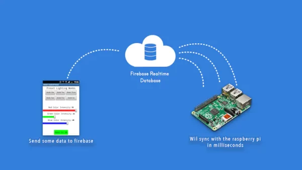
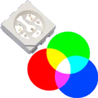
Today’s tutorial is about controlling any RGB LED Strip ambient light wirelessly over Wifi using a custom-built Android application connected with the Raspberry Pi board through the Firebase database. To build this project, we need to deal with some stuff like building an Android mobile app, building a Firebase database server, connecting the Raspberry Pi and the Android app together through Firebase, taking different actions based on incoming data, power management, and electronics wiring. Don’t worry; we will cover all these topics in detail in today’s tutorial. So, bear with me; I promise it will be worth it!
How does the project work?

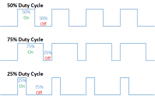
- Period: It’s the sum of the HIGH (3.3V) time and the LOW(0V) time.
- Duty Cycle: It’s the percentage of time where the signal was HIGH (3.3V) during the time of period.
Enough Theory! Let’s make some stuff. Let’s take a look at the wiring diagram.
Wiring Diagram
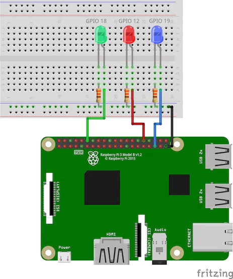
The wiring diagram is very simple, connect each LED on a different PWM pin.
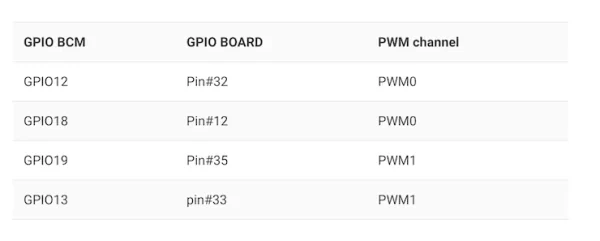
- Red LED –> GPIO 12(PWM0).
- Green LED –> GPIO 18(PWM0).
- Blue LED –> GPIO 19(PWM1).
The raspberry pi has two different schemes in numbering its GPIO pins. you can use either pin numbers (BOARD) or the Broadcom GPIO pin numbers (BCM). You can only use one numbering scheme in each program.
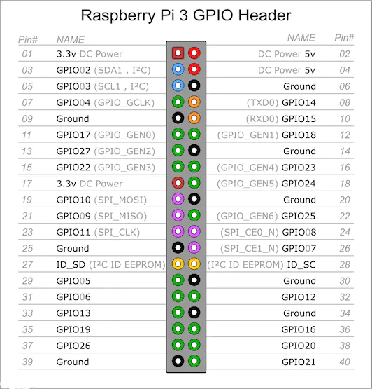
GPIO Board: Referring to the pin by its number of the plug, the pin number on the physical board which printed on it. Example: PIN#1, PIN#2, …..
GPIO BCM: Referring to the pin by its “Broadcom SOC Channel” number, these are the numbers after the GPIO word. Example: GPIO12, GPIO19, ….
Neither way is wrong, both ways are good and working well without any differences. You have to pick the one which you feel comfortable more with.
The Raspberry Pi 3 Model B has two PWM channels (PWM0, PWM1) each channel has two different GPIO PWM pins available for use.
Code
import RPi.GPIO as GPIO
from time import sleep

redLED = 18
blueLED = 12
greenLED = 19

GPIO.setwarnings(False)
GPIO.setmode(GPIO.BCM)

GPIO.setup(redLED,GPIO.OUT)
GPIO.setup(blueLED,GPIO.OUT)
GPIO.setup(greenLED,GPIO.OUT)

red_pwm = GPIO.PWM(redLED,1000)
blue_pwm = GPIO.PWM(blueLED,1000)
green_pwm = GPIO.PWM(greenLED,1000)

red_pwm.start(0)
blue_pwm.start(0)
green_pwm.start(0)

print("AH Shit! Here we go again! Press CTRL+C to exit")

try:
    while True:
        for duty in range(0,101,1):
            red_pwm.ChangeDutyCycle(duty)
            sleep(0.01)
        sleep(0.5)

        for duty in range(100,-1,-1):
            red_pwm.ChangeDutyCycle(duty)
            sleep(0.01)
        sleep(0.5)

        for duty in range (0, 101, 1):
            blue_pwm.ChangeDutyCycle(duty)
            sleep(0.01)
        sleep(0.5)

        for duty in range (100, -1, -1):
            blue_pwm.ChangeDutyCycle(duty)
            sleep(0.01)
        sleep(0.5)

        for duty in range(0,101,1):
            green_pwm.ChangeDutyCycle(duty)
            sleep(0.01)
        sleep(0.5)

        for duty in range(100,-1,-1):
            green_pwm.ChangeDutyCycle(duty)
            sleep(0.01)
        sleep(0.5)

except KeyboardInterrupt:
    red_pwm.stop()
    blue_pwm.stop()
    green_pwm.stop()
    GPIO.cleanup()
Code Explanation
The code is pretty simple and straight forward, first we need to import two important modules to allow us to use the raspberry pi GPIO pins. Also, import the time module that will make the timing work for us. without importing this module you will not be able to use the sleep() method.
import RPi.GPIO as GPIO
from time import sleepredLED, blueLED, greenLED referring to the three PWM pins that we will use to control our LEDs. Yeah as you noticed we are using the GPIO BCM numbering scheme.redLED = 18
blueLED = 12
greenLED = 19GPIO.setmode(GPIO.BCM)
GPIO.setup(redLED,GPIO.OUT)
GPIO.setup(blueLED,GPIO.OUT)
GPIO.setup(greenLED,GPIO.OUT)red_pwm, blue_pwm, green_pwm with 1000Hz frequency that will help us to generate the PWM signal. After that, we need to set the initial state of these pins to 0% duty cycle which means that the three pins will be OFF at the beginning of the program.red_pwm = GPIO.PWM(redLED,1000)
blue_pwm = GPIO.PWM(blueLED,1000)
green_pwm = GPIO.PWM(greenLED,1000)
red_pwm.start(0)
blue_pwm.start(0)
green_pwm.start(0)Here is the fun part! inside the while loop we write the set of commands(program) that we need to keep executing forever until we force-stop it.
inside the “while loop” implement a for loop it’s initial value 0, at every iteration, it will increment by 1 until it reaches 100. This for loop responsible for increasing the red LED light brightness.
while True:
    for duty in range(0,101,1):
        red_pwm.ChangeDutyCycle(duty)
        sleep(0.01)
    sleep(0.5)
The second “for loop” it’s initial value 100, at every iteration will decrease by 1 until it reaches 0. this for loop is responsible for decreasing the red LED light brightness.
for duty in range(100,-1,-1):
        red_pwm.ChangeDutyCycle(duty)
        sleep(0.01)
    sleep(0.5)
then repeat the previous logic with the remaining two LEDs. After finishing your code, close and save it, run it by writing python fileName.py in the terminal.
After running it, It’s expected to see this sentence got printed on the terminal AH Shit! Here we go again! Press CTRL+C to exit then the three LEDs light brightness will start to increase and decrease.
I will assume that you did that and it’s working fine with you. VOILA! Officially you now promoted to the next level. Let’s make it more interesting and control the beefy RGB LED Strip.
Control RGB LED Strip Lighting
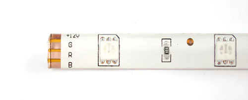
RGB LED Strip pinout

Power Management

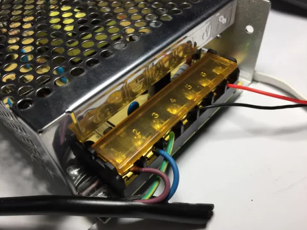
And we connect them as follow:
- Brown wire (AC Power source): L (Power supply).
- Blue wire (AC Power source): N (Power supply).
- Green wire (AC Power source): Earth (Power supply).
And the red, and the black wire are the 12VDC output:
- Red Wire: 12VDC Output (V+).
- Black Wire: GND Output (V-).
Wiring Diagram
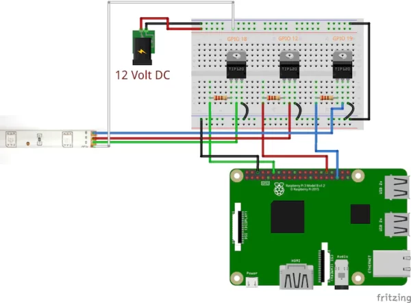
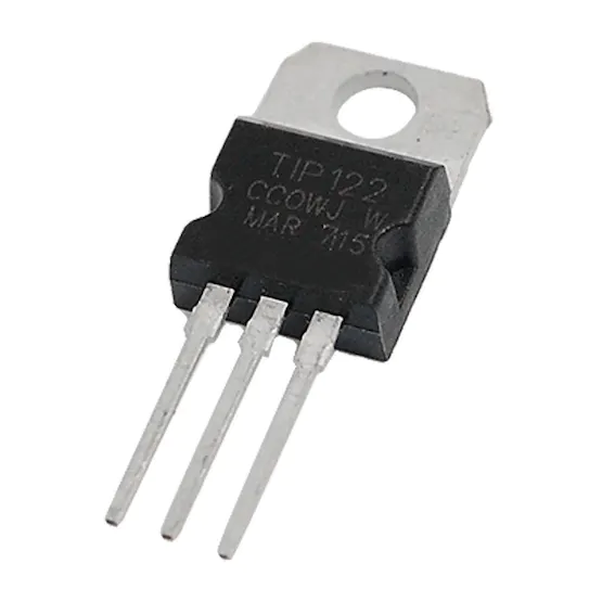
Here comes the TIP122 Darlington transistor, this transistor can drive high power loads by using a small amount of current and voltage.
The TIP122 transistor can handle current up to 5A(Continous) and 8A(Peak) which satisfies our needs.
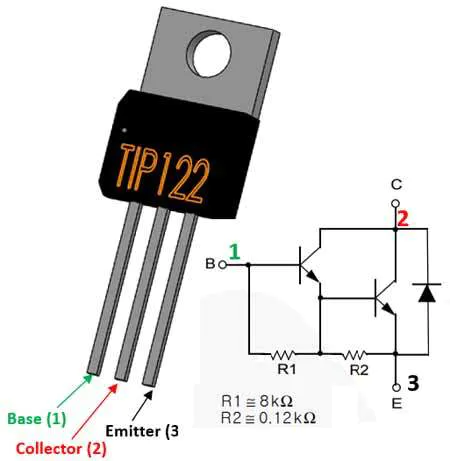
TIP122 Transistor Pinout
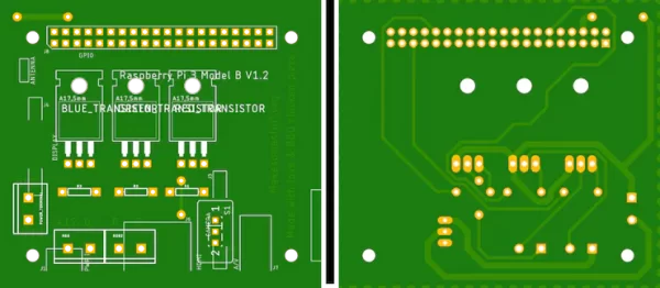
You can order your own PCB From PCBWay company these guys have a very good reputation in this field and they ship to more than 170 countries around the world with reasonable prices. all you have to do is to open the project PCB files link and click “Add to cart”. That’s it!
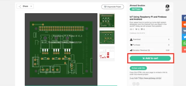
This PCB can get mounted over the Raspberry pi board easily as a normal raspberry pi HAT, it will organize your wiring and will make your project more easy to debug.
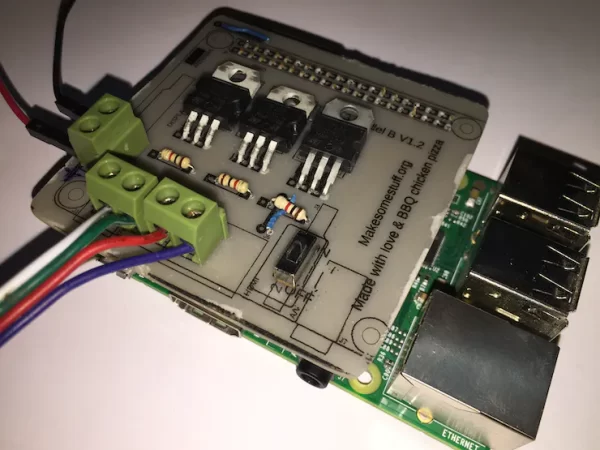
With that slide switch, you can turn on and off the RGB LED Strip power.
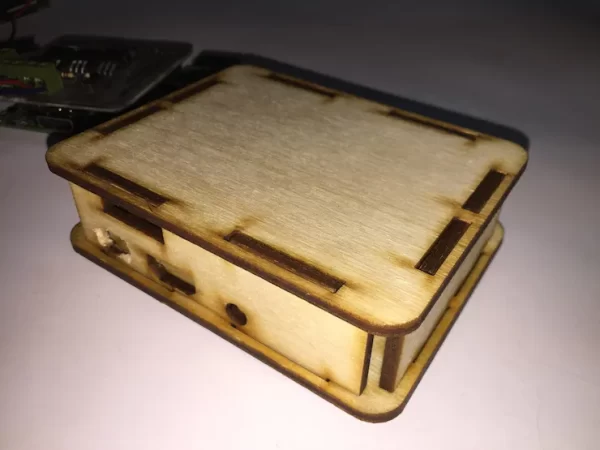
Raspberry Pi Enclosure
I designed a laser cutting enclosure using Autodesk fusion 360, feel free to download the DXF files from this link.
Code
We will use the same previous Code without any changes.Code Explanation
The same previous explanation since we are using the same code with the same logic.
After finishing the wiring and your code, close and save it, Run your program by writing python fileName.py in your terminal. Like the last example, After running your program, It’s expected to see this sentence got printed on the terminal AH Shit! Here we go again! Press CTRL+C to exit then the three LEDs light brightness will start to increase and decrease.
After getting sure that everything is working as expected, let’s level it up and build our firebase database.
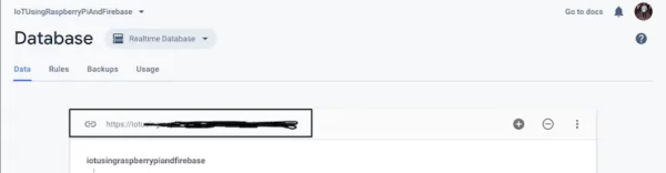
Building The Firebase Database
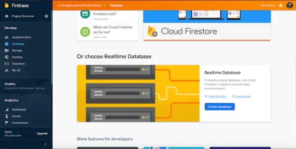
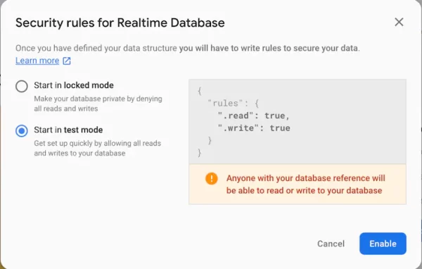
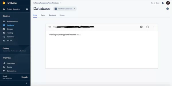
The Firebase Realtime Database is a cloud-hosted database. Data is stored as JSON and synchronized in realtime to every connected client. If you want to know more check out this link.
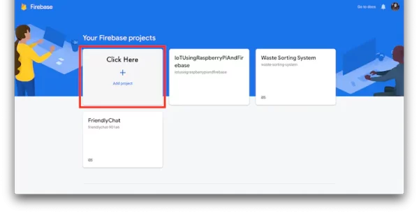
As we stated before, the realtime database will receive some data from the mobile app based on the user interaction and will sync it with the raspberry pi in milliseconds. So, to be able to use firebase you need to sign in using your normal Gmail account. then go to your project console to create a new project.
First things first, you need to create a new project in your console.


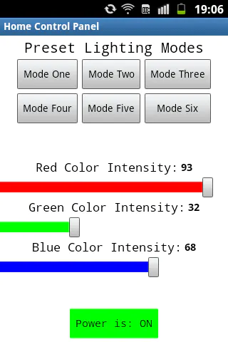
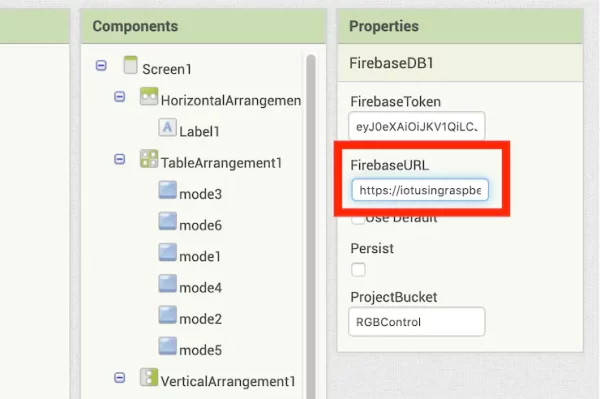
Building The Android Mobile APP
To build the mobile app that the user will use to control the RGB LED Strip from, you can use the amazing tool called “MIT App Inventor”. It’s fast and very easy to use. App Inventor lets you develop Android mobile applications using a web browser and a physical mobile phone or just the emulator. The MIT App Inventor saves your projects in their clouds to keep tracking your work.
To get started, you need to go to the MIT App Inventor official website and login with your Gmail account. Then press on the “Create Apps” button and start building your mobile app. It’s that easy!
To build your mobile app using the app inventor tool, you should deal with two main parts.
- The design of the app.
- The programming of the app.
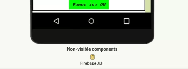
The App Design