Implement a project that converts a Raspberry Pi into an OBD2 on-board diagnostic tool. This will be achieved by using the Pi-OBD add-on board or DXM OBD2 module and OBD2 software from a previous project, ‘Firmware Update for OBD2-Analyser NG’. The resulting device will allow the Pi to access and retrieve OBD2 vehicle data, as well as read and clear diagnostic trouble codes related to emissions and reset inspection/maintenance associated data.
Preface
For those who may have come across one of my previous OBD2 projects, you may recall that it offered firmware and software (including Mingw32 and Raspbian) for the OBD2-Analyser NG, which was featured in the September 2009 issue of Elektor magazine. While that project had its merits, it also presented a significant limitation: the necessary hardware is no longer readily available. My new OBD2 project aims to rectify this issue, providing a solution that directly addresses this problem.
The OBD2-Analyser NG utilizes a DIAMEX DXM OBD2 module, aligned with a vehicle bus on one side and offering a serial interface on the other. The Raspberry Pi, meanwhile, boasts a serial interface accessible through its GPIO pins, working harmoniously at 3.3V line drivers and straightforward to connect. Inspired by this compatibility, I conceived the idea of creating a simple add-on board for the Pi by integrating a DXM OBD2 module. Although I lacked a spare DXM OBD2 module, I found an innovative workaround to utilize the existing one on my OBD2-Analyser NG.
Specifically, the serial interface of the DXM OBD2 module is linked to an AVR AT90CAN128 microcontroller, whose free port is available at the OBD2-Analyser NG’s expansion pin header. I implemented a straightforward firmware modification to redirect DXM data from the serial interface to the accessible port pins and vice versa. Following this development, I connected the pins to the PI’s serial interface GPIOs, enabling me to effectively control the DXM on the OBD2-Analyser NG using my OBD2 software running on the PI.
After sharing this exciting development with DIAMEX, they kindly sponsored my project with a complimentary DXM OBD2 module, which I employed to create a breadboard prototype. Additionally, DIAMEX designed a Pi-OBD add-on board based on their cutting-edge AGV OBD2 module, the successor to the DXM module. I subsequently integrated support for the AGV module into my OBD2 software. As a result, there are now two distinct options to integrate OBD2 functionality with the Raspberry Pi, thanks to the collaboration and generosity of DIAMEX.
Variant 1: OBD2 for Raspberry Pi using the DIAMEX Pi-OBD add-on board
- Pi-OBD add-on board (*)
- OBD2 cable (*)
- 7″ touchscreen (**)
- Raspberry Pi/Raspbian with free serial device, e.g. /dev/ttyAMA0 or /dev/ttyS0
- HHGui OBD2 software for the Pi
(*) Pi and display are powered via the OBD2 cable
(**) displays connected via the HDMI ribbon cable are recommended, other displays need some hardware hacks
Variant 2: OBD2 for Raspberry Pi using the DIAMEX DXM OBD2 module
- DXM OBD2 module
- A few additional parts like PCB (a breadboard will do), wires, connector for GPIOs, and connectors for OBD2 cable, optional but recommended: 2 resistors, 1 capacitor, 1 diode
- OBD2 cable
- Vehicle 12V socket to USB adapter + USB cable to power the Pi and the display
- Raspberry Pi/Raspbian with free serial device, e.g. /dev/ttyAMA0 or /dev/ttyS0
- Display for the Pi (minimum display size 320 x 165 pixels) (*)
- HHEmu OBD2 software for the Pi
(*) displays connected via the HDMI ribbon cable are recommended, other displays that occupy (but do not use) the Pi’s serial interface require 2-3 mini-clips to get access to the serial interface and GND. Instead of mini-clips, wires soldered to the pins on the bottom side of the Pi are recommended for a reliable connection. If a display uses the first 26 pins only, GND can be connected to pin 30, 34 or 39.
1. The DIAMEX Pi-OBD add-on board
The Pi-OBD add-on board is a comprehensive solution that combines the DIAMEX AGV OBD2 interface with a reliable, automotive-certified power supply and voltage regulator for the AGV, Raspberry Pi (B+, 2, and 3), and display, all integrated onto a single PCB. This compact add-on board is powered directly through the OBD2 cable. It features two OBD2 cable connectors: a 2×5 box header and a 9×1 male pin header. Please note that only one connector can be used at a time. The AGV OBD2 interface on the Pi-OBD add-on board is an advanced interface that builds upon the DXM, offering enhanced configurability.
The AGV interface supports the following OBD2 protocols:
- SAE J1850 PWM and VPW
- ISO 9141 (keyword protocol with 5-baud wakeup)
- ISO 14230 (KWP2000 with 5-baud wakeup or fast initialisation)
- ISO 15765 (CAN with 11 or 29 bit identifier and 250 kbit/s or 500 kbit/s baud rate)(*)
(*) The baud rate of the CAN protocols with 11 or 29 bit identifier and default 250 kbit/s baud rate is configurable.
The Pi-OBD utilises a limited number of GPIO pins, with some additional functionality covered. Consequently, it’s advisable to use a display connected via an HDMI ribbon cable. Nonetheless, since the SPI GPIOs are not employed by the Pi-OBD, it’s feasible to design an adapter to enable displays that use the SPI protocol to be integrated.
Pi Pins and GPIOs connected to an 8×1 female header on the Pi-OBD:
- Pin 2: +5V
- Pin 4: +5V
- Pin 6: GND
- Pin 8: GPIO 14 – serial interface Tx
- Pin 10: GPIO 15 – serial interface Rx
- Pin 12: GPIO 18 – used for Pi-OBD module reset (pin low = reset, pin high = no reset)
- Pin 14: GND
- Pin 16: GPIO 23 – used for bootloader access (pin high + module reset = bootloader activated for Pi-OBD firmware update)
Pins 1, 3, 5, …, 15 are covered by the Pi-OBD, but the Pi-OBD contains holes for mounting a connector in case a display or other hardware needs access to these pins.
A 2×1 male pin header for +5V and GND is available on the Pi-OBD to power the display.
The Pi-OBD add-on board contains 4 holes on the PCB matching the 4 holes on the Pi B+, 2 or 3. So, it can be mounted using 4 spacers and 4 screws.
2. The DXM OBD2 Module Add-on Breadboard
The DXM OBD2 module has been familiar to Elektor readers through its appearance in the OBD2-Analyser NG project featured in the September 2009 issue of Elektor magazine, as well as the Wireless OBD2 project published in the April 2011 issue. This module is still obtainable from www.diamex.de, which also provides updated firmware. Moreover, you can purchase an OBD2 cable from the same source.
My DIY add-on board is comprised of a DXM OBD2 module, a 9-pin male pin header for OBD2 cable connectivity, a 3-pin male pin header for the serial interface, and a few connecting wires. For added protection, I added a diode in the +12V line to prevent reverse voltage damage, a small blocking capacitor near the DXM’s power supply pins, and two resistors in the serial Tx/Rx lines to safeguard against wiring errors. If you’re interested in seeing the wiring diagram between the DXM and OBD2 connector, I recommend consulting the official documentation provided by the DXM manufacturer. Additionally, readers familiar with the OBD2-Analyser NG article may recall that schematics illustrating the same wiring configuration, along with a 1N4004 diode, a 10µF/63V capacitor, and a 330 Ohm resistor, were included in that publication.
If you use bent pin headers and arrange the DXM and additional components in a flat configuration, you’ll likely be able to mount the add-on board in reverse, allowing it to fit comfortably under a display.
2.1 Wiring
The DXM module utilises the 12V power supply from the OBD2 connector, and is equipped with an onboard 3.3V voltage regulator. Ensure that you connect the output of the 3.3V voltage regulator to the 3.3V input on the module. If you’re only using the OBD2 tester in vehicles that employ CAN protocols, and you don’t need to support PWM/VPW or K-line protocols, you won’t need to make those specific connections.
OBD2 connector                                           DXM module                          Raspberry Pi
Pin   2 PWM/VPW+  -----------------------------  Pin  2 PWMP
Pin 10 PWM/VPW-  ------------------------------  Pin  3 PWMM
Pin   4 Chassis GND  ---------------------------  Pin  4 GND  ---------------------  Pin  6 Ground
Pin   5 Signal GND - Pin 4 Chassis GND
Pin   6 CAN-High  --------------------------------  Pin 32 CANH
Pin 14 CAN-Low  ---------------------------------  Pin 31 CANL
Pin   7 K-Line  -------------------------------------  Pin 33 KLINE
Pin 15 L-Line  -------------------------------------  Pin 34 LLINE
Pin 16 12V  --------  >|- diode ----------------  Pin   1 12V - capacitor - Pin 4 GND
                                  Pin   9 3V3OUT - Pin 14 3V3IN
                                                                         Pin 24 TXD ----- resistor ----- Pin 10 GPIO 15 Rx
                                                                         Pin 25 RXD ----- resistor ----- Pin   8 GPIO 14 Tx
Note: The DXM and AGV modules come equipped with a command that returns the voltage measured at the module’s power supply input. However, when using a diode for reverse voltage protection, keep in mind that the reported voltage is not equivalent to the actual battery voltage. This is due to the diode’s inherent forward voltage drop. For the specific silicon diode used, this drop is at least 0.7V and increases with current. As a result, when accessing the system information menu within the HHEmu OBD2 software, the DXM-Voltage displayed will be lower than the actual battery voltage.
3. Raspberry Pi
So far, I have tested the add-on boards and the OBD2 software using the following setup:
- Raspberry Pi 2/Raspbian, official 7″ touchscreen, Pi-OBD add-on board or DXM add-on breadboard
- Raspberry Pi 3/Raspbian, Waveshare/Joy-it 3.2″ touchscreen, Pi-OBD add-on board or DXM add-on breadboard (*)
(*) Since I did not use bent pin headers, the DXM add-on breadboard does not fit under the display.
Due to the absence of an adapter, the Pi-OBD add-on board cannot be installed under the display. However, it can be mounted to the right or top of the Pi, utilizing only 2 spacers instead of the standard 4. Additionally, the Pi-OBD add-on board does not power the Pi and display in my setup, as I did not connect the 5V supply. To connect the Pi-OBD, I soldered a 2×1 male pin header to the Tx/Rx pins at the bottom of the Pi 3 and routed the Rx/Tx signals from the Pi-OBD to these pins. The GND connection is made at pin 39. Furthermore, I connected the Pi-OBD’s reset and bootloader pins to GPIO 12 (pin 32) and GPIO 16 (pin 36), respectively. The 3.2″ display, being relatively small, leaves pin 32, 36, and 39 accessible, allowing for easier connection and configuration.
On both Pis I use the serial device /dev/ttyAMA0. Usually, that device is already used by the Pi and you have to free it.
On the Pi 3 you additionally have to reconfigure or disable Bluetooth to make that device available. Read the serial interface configuration section in the file Readme_raspberry.txt that is part of the attached OBD2 software zip-file.
4. OBD2 Software for the Pi
The OBD2 software utilizes the OBD2-Analyser NG firmware, which only communicates with DXM modules. Adding support for AGV in the real firmware would necessitate significantly increasing the limited FLASH memory. To avoid this, I created a separate version for AGV using a define HHEMU_OBD_PI in the makefile. In this AGV-specific version, I removed non-essential menus and features from the OBD2-Analyser NG, such as beeps, Bluetooth, USB, Serial interface, and DXM simulator modes, as they are of little relevance for this application.
It’s crucial to use different versions of the OBD2 software depending on the add-on board you’re employing. The Pi-OBD add-on board requires the HHGui software, whereas the DXM add-on board necessitates the use of the HHEmu software.
To run the OBD2 software, the window requires a minimum resolution of 640×330 pixels. However, if the software is able to read a background image during initialization, the recommended window size is slightly smaller, at 320×165 pixels.
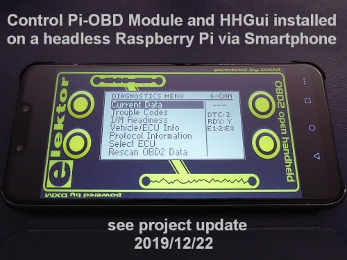
4.1 HHGui OBD2 Software
HHGui is an acronym for Pi-OBD2 Handheld GUI, which suggests that it resembles a real OBD2 handheld tester, such as the OBD2-Analyser NG. Interestingly, HHGui utilizes the same background image feature found in HHEmu. When the program starts, if the file HHGuiBackgroundPic.png is detected, the simulated LCD screen of HHGui is overlaid onto a scanned image of the real OBD2-Analyser NG LCD area. Additionally, the OBD2-Analyser NG buttons displayed in the background image function as operational buttons when touched on a touchscreen, further reinforcing the illusion of a real handheld. It’s worth noting that you can create your own custom background image as long as you maintain the original size and button positions, which can be used with HHGui.
Start HHGui with
./hhgui device 115200 init=AGVUsually, device is one of /dev/ttyAMA0, /dev/ttyS0 (Pi 3 miniUART) or /dev/serial0. The device must be free and configured (see chapter 3 above).
Further self-explanatory command line options like fullscreen or maximize combined with nocursor can be given.
If you start HHGui without background image, touchscreen control differs. Then, the visible window area is divided into 4 rectangular regions.
- Clicking or touching the top left area is like pressing the Up button.
- Clicking or touching the bottom left area is like pressing the Down button.
- Clicking or touching the top right area is like pressing the ESC button. (*)
- Clicking or touching the bottom right area is like pressing the OK button.
That allows to use even small touchscreens with 320 x 240 pixels.
The top-right region of the screen features a small, 30×30 pixel area that is not immediately visible. By clicking or touching this area, the HHGui program switches between full-screen mode and standard window size. This functionality is essential for seamlessly closing HHGui on a touchscreen, even when in full-screen mode, which typically lacks a closing mechanism.
In some menus long-pressing/touching the button areas has a special meaning. E.g. long-pressing Up/Down in a list, will make a page scroll.
Long-pressing ESC makes a software reset. Then, HHGui displays the start screen and jumps to the main menu.
When you launch HHGui without specifying a device and baud rate, such as running the command./hhgui, the program enters OBD2 simulator mode. In this mode, you can explore and test all menu items and OBD2 services supported by HHGui. Additionally, many OBD2 parameters, like the number of diagnostic trouble codes, can be configured using a keyboard or virtual keyboard for inputting commands. If you’re interested in learning more about the available commands, please refer to my other OBD2 project’s HHEmu command summary chapter.
4.2 HHEmu OBD2 Software
The OBD2 software named HHEmu is described in detail in my other Labs project here: http://www.elektormagazine.com/labs/firmware-update-and-emulator-for-obd2-analyser-ng-wireless-obd2
Start HHEmu with
./hhemu device init=DXMThat is identical to
./hhemu device 9600 init=DXMUsually, device is one of /dev/ttyAMA0, /dev/ttyS0 (Pi 3 miniUART) or /dev/serial0. The device must be free and configured (see chapter 3 above).
Other command line options are identical to the HHGui options described above.
4.3 Other Ways to start HHGui/HHEmu
In addition to the initial console startup, you may also encounter other scenarios: automatically launching HHGui or HHEmu on desktop startup, accessing HHGui or HHEmu through a desktop menu entry, or starting HHGui or HHEmu by double-clicking a start script.
Create/edit a file
nano /your_path_to_obd2_software/startobd.shDepending on the start with or without background image it should contain the following lines:
OBD2 software with background image
cd /your_path_to_obd2_software
./hhgui /dev/ttyAMA0 115200 init=AGV nocursor maximize
or
cd /your_path_to_obd2_software
./hhemu /dev/ttyAMA0 init=DXM nocursor maximize
OBD2 software without background image
./hhgui /dev/ttyAMA0 115200 init=AGV nocursor fullscreenor
./hhemu /dev/ttyAMA0 init=DXM nocursor fullscreenCorrect the path to your HHGui/HHEmu directory and depending on your setup correct the serial device.
If the file is not executable, enter chmod +x ./startobd.sh
If you use a system directory, you need sudo chmod +x ./startobd.sh
4.3.1 Auto start HHGui/HHEmu in Desktop
There are several ways to do that. The one that works for me is:
Start editor with
sudo nano ~/.config/lxsession/LXDE-pi/autostartinsert
@lxterminal -e /your_path_to_obd2_software/startobd.shbefore the @xscreensaver line
save and exit.
Reboot to test it.
4.3.2 Start HHGui/HHEmu via Desktop Menu Entry
Copy a xxx.desktop file from /usr/share/applications to another directory.
Change to that directory.
Rename the file to hhgui.desktop or hhemu.desktop and edit the file.
Change the Name line to
Name=HHGui
or
Name=HHEmu
Change the Exec line to
Exec=lxterminal -e /your_path_to_obd2_software/startobd.shChange all other lines to your needs. Especially, select a meaningful icon or create one.
Save the file, copy or move it back to /usr/share/applications (you need sudo to do that).
A new desktop menu entry HHGui or HHEmu will show up.
4.4 OBD2 Diagnostic Services supported by HHGui/HHEmu
A crucial aspect of OBD2 onboard diagnostics is defined by the ISO 15031-5:2015 standard, which is built upon the SAE J1979 standard. The full title of the standard is ‘Road vehicles – Communication between vehicle and external equipment for emissions-related diagnostics – Part 5: Emissions-related diagnostic services.
These diagnostic services solicit emissions-related data from 1 to 8 OBD2 electronic control units (ECUs). The primary electronic control unit providing OBD2 data is the engine control unit (also referred to as the ECU). For clarity, it’s better to refer to it as the engine control module (ECM). Additionally, for vehicles with automatic transmission, the transmission control module (TCM) can also supply emissions-related data.
The standard defines diagnostic services that are identified by a Service ID (SID). Most of these services offer various functionalities that are addressed by a Function Identifier. The type of identifier used depends on the specific SID, and it can be either a Parameter ID (PID), Test ID (TID), On-Board Diagnostic Monitor ID (OBDMID), or Vehicle Information Type (INFOTYPE).
HHGui and HHEmu support the following diagnostic services:
Service 0x01 – Request current powertrain diagnostic data
This service is employed to request real-time data, including vital signs like vehicle speed, engine RPM, coolant temperature, oil temperature, and boost pressure. Additionally, it can also retrieve static data, such as the exact location and number of oxygen sensors, as well as inspection/maintenance readiness monitors.
The sensor data provided is raw and untouched, meaning it hasn’t been adjusted or processed for use in a gauge. This means that you’ll receive the actual raw value, rather than the value displayed on the speedometer.
Service 0x02 – Request powertrain freeze frame data
This service is employed to retrieve a collection of saved data linked to a diagnostic trouble code (DTC) that triggered freeze frame storage. Certain DTCs prompt the capture of current data at the time the error occurred. This collected data is referred to as freeze frame data and can be examined later to investigate the root cause of the fault.
This service is utilized to retrieve confirmed diagnostic trouble codes (DTCs). A DTC receives the confirmed status when it is caused by a misfire that may harm the catalyst or if two consecutive driving cycles under the same conditions indicate a fault detected by the ECU. A confirmed DTC is communicated to the driver via the malfunction indicator light (MIL). A steady light signals a fault that allows driving to the next workshop, whereas a blinking light signifies a fault that may cause further damage if driven on.
This service clears confirmed and pending diagnostic trouble codes (DTCs), I/M readiness monitors, freeze frame data, and additional information. Additionally, it deactivates the malfunction indicator light (MIL). Following this service, a vehicle is no longer ready for inspection and requires further driving to compile the required data, as the supported I/M readiness monitors need time to verify their status.
Note that certain vehicles or ECUs demand the ignition to be on and the engine to be off for this service to succeed. It is crucial to avoid utilizing this service unnecessarily, as it may not be effective. The service 0x01 PID 0x30, which returns the number of warm-ups since diagnostic trouble codes were cleared, and the service 0x01 PID 0x31, which returns the distance traveled since diagnostic trouble codes were cleared, will indicate when the data has been cleared.
Service 0x07 – Request emissions-related diagnostic trouble codes detected during current or last completed driving cycle
This service reads pending diagnostic trouble codes. It’s particularly useful after repair to verify whether a defect has been successfully resolved. By using this service, you can bypass the need to drive for two consecutive cycles to fetch confirmed DTCs, which would otherwise be displayed after a set amount of time.
Service 0x09 – Request Vehicle Information
Utilize this service to retrieve essential vehicle data, including the Vehicle Identification Number (VIN), Software Calibration IDs (CALIDs), Software Calibration Verification Numbers (CVNs), and In-Use Performance Tracking (IPT) information. IPT data provides statistical insight into the vehicle’s performance, such as ignition cycle counts and OBD2 monitor run frequencies, along with the ECU name.
Service 0x0A – Request emissions-related diagnostic trouble codes with permanent status (CAN protocols only)
This service retrieves permanent diagnostic trouble codes. Each confirmed DTC sets a permanent DTC after an ignition cycle concludes. Permanent DTCs cannot be erased by executing service 0x04 or disconnecting the battery. Instead, they are automatically cleared by the ECU after the error condition for a fault has been absent for multiple consecutive driving cycles, indicating that the problem has been resolved.
The services 0x05, 0x06 and 0x08 not described here are not supported by HHGui/HHEmu yet.
Important note: OBD2 diagnostic services are not intended for configuring vehicle settings. Additionally, it’s crucial to understand that aside from the Malfunction Indicator Light (MIL), no other warning lights can be reset utilizing OBD2. To perform configuration-related tasks, such as resetting service intervals, clearing airbag fault lights, or configuring door locking, manufacturer-specific diagnostic services must be employed. OBD2 cannot be used for these purposes.
5. Proof of Concept (The full Story)
I didn’t have a spare DXM OBD2 module at hand, but I utilized the one from the OBD2-Analyser NG project published in the September 2009 issue of Elektor magazine. This module is unique in that it can be utilized without desoldering, and it’s connected to the USART0 of an AVR AT90CAN128 via its serial interface. When in Bluetooth mode, the latest official firmware v1.2.1 serves as a gateway, forwarding USART0 data to Port F, Pin 7, which is connected to the serial interface of a BTM-222 Bluetooth module. In the receive direction, the firmware reads data from the BTM at Port F, Pin 6 and relays the data to USART0, which transmits it to the DXM.
For a rapid test, I leveraged the existing gateway mechanism, but modified it to utilize the free port F, pins 1 and 2, which are conveniently accessible at the J2 extension header pins 2 and 3 on the OBD2-Analyser NG. Additionally, ground is available at the J1 extension header pin 1.
The serial interface of the Pi uses GPIO 14 (pin 8) for the Tx line and GPIO 15 (pin 10) for the Rx line. Ground is available at pin 6.
So, for the test I made the following connections:
Raspberry Pi OBD2-Analyser NG AT90CAN128
Ground pin 6 extension header J1 pin 1 Ground
Tx GPIO 14 pin 8 extension header J2 pin 3 Rx port F bit 2
Rx GPIO 15 pin 10 extension header J2 pin 2 Tx port F bit 1
For the connections, I employed a breadboard and inserted small 200 Ohm resistors in the Tx and Rx lines to safeguard against potential damage from incorrect wiring. As illustrated in the attached image, these precautions ensured a safe connection.
This is the setup for the hardware test. The software modifications have been integrated into my OBD2-Analyser NG firmware update v1.7.1. The outcome is a novel Serial Interface Mode accessible via the primary menu of the firmware. Prior to accessing the Serial Interface Mode option in the main menu, ensure that the related checkbox has been activated in the settings menu.
After updating the firmware, you can connect the OBD2-Analyser NG to a vehicle or 12V power source. Once connected, navigate to the Serial Interface Mode menu to enable the gateway routes mentioned above.
The HHEmu OBD2 software also requires some modifications. These changes are incorporated into HHEmu v2.80. When started with a serial device specified on the command line, HHEmu will wait for a prompt from the other side. Since the DXM in my test setup is not directly connected, it won’t recognize the connection to the Raspberry Pi. It remains connected to USART0 of the AT90CAN128 and won’t send a prompt, as it has already sent one that was read by the OBD2-Analyser NG before entering Serial Interface Mode. To address this issue, I introduced the nosync command line option. However, if you’re connecting a DXM module directly to the Raspberry Pi, this modification isn’t necessary. In that case, you’ll need to use the init=DXM command
To increase usability, I added a command line option to make the baud rate customizable. By default, HHEmu aims to connect to a (virtual) serial interface with a 9600 baud rate and 8 data bits, 1 stop bit setting. As per the DXM documentation, the DXM module comes with a factory setting of 9600 baud. Coincidentally, this matches the standard configuration. Nonetheless, during the OBD2-Analyser NG initialization process, the DXM baud rate is modified to 19200 baud by the firmware. As a result, in my test setup, the DXM module operates at a 19200 baud rate.