
How Do I FPGA?
I’ve been thinking about building stuff with FPGA’s for a while, and usually get turned away because FPGA’s are considerably harder to implement than microcontrollers since they have no on-chip memory. It is necessary to re-program the gates every time they power up, which requires an external flash memory chip. There aren’t great references online for the DIY community, so I figured I’d post how to get this working. Not using dev boards opens a world of opportunities, so I’m a proponent of not using Arduino’s and their FPGA equivalent for too long (sure, they’re good to get started with, but don’t become dependent)
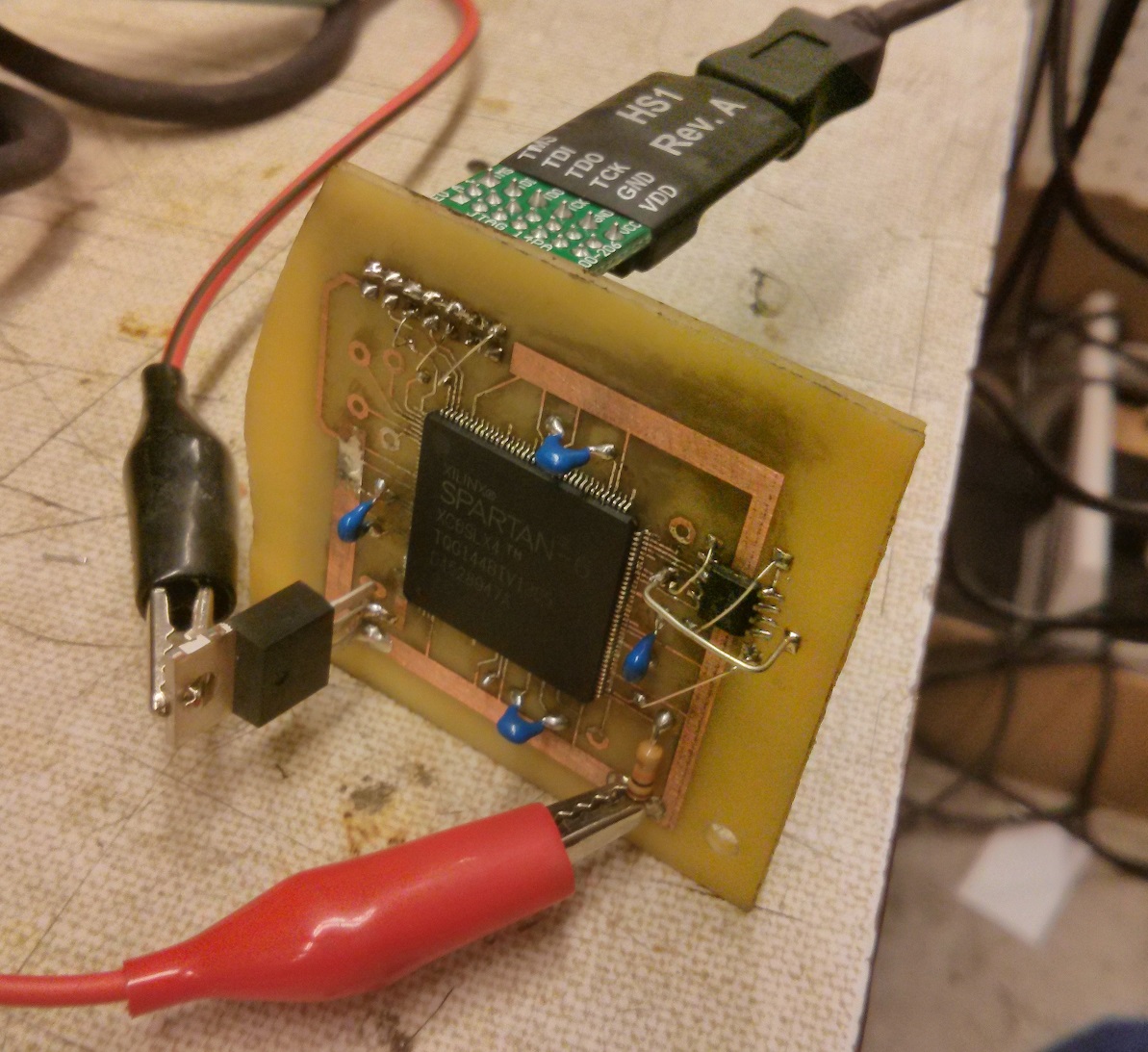
Not wanting to screw up an expensive complex board by being a first-timer at putting an FPGA into a circuit, I figured I’d build a little test board with the cheapest Spartan 6 you can get (about $10), which comes in a solderable TQFP144 package. Sadly, most high end FPGA’s are BGA and therefore quite hard to solder as a DIY project.
There are quite a few ways to program an FPGA. The most common would be direct programming, indirect programming, and processor programming. Direct programming is where there is a PROM chip which is programmed over JTAG, and the PROM chip programs the FPGA at boot. Indirect programming is where there is a PROM chip attached to the FPGA, and JTAG also connects to the FPGA. In this scenario, JTAG can either directly program the FPGA, or load a temporary PROM-programmer application onto the FPGA which programs the PROM and then restarts. The operational differences are subtle, but the circuit is quite different. Processor programming is where a microcontroller on the board performs the task of programming the FPGA, which would require custom code in the microcontroller as well as requiring you to have a micro at all. While substantially more advanced, this is way more powerful because the microcontroller can dynamically reprogram the FPGA on the fly for different tasks.
For this project, I’m going to use indirect programmimng, because it’s about $8 cheaper than direct programming, and processor programming is vastly overcomplicated for what I want to do.
The first task is to select a PROM chip. There are a number of series that are recognizable by the XILINX iMPACT tool. The M25P series is cheapest and very popular. You’ll need to read the datasheets to figure out how much memory your FPGA needs. I’m using the Spartan LX9 in my production board (although LX4 on this test board since it’s half the price), so I selected a 4M PROM. The M25P40 is only 67 cents on digikey in qty 1!
I’m using the Digilent JTAGHS1 programmer, since it’s the cheapest programmer that’s guaranteed compatible with Xilinx iMPACT (the programming application provided in ISE, the Xilinx IDE). At $55, it’s not the cheapest thing but you only have to buy it once and it’s way cheaper than the Xilinx brand programmers.
Here is the minimum schematic to hook it up to a Spartan 6 for JTAG programming. Other micros will have slightly different configuration bits, but the concept will be the same:
P144, HSWAPEN, if low enables a pullup resistor on all pins during configuration so any tristate devices are defined. You’d probably want to do this.
When P69 M0 is high and P60 M1 is low, the chip is configured for indirect programming over JTAG. Other M-configurations would be for other programming modes such as direct programming. For other chips, you’ll just have to look up whatever configuration bits your chip uses.
P37, PROGRAM_B_2 is the main chip reset pin. It should be pulled up, and to reset pulled low.
P71 DONE is a “done programming” output indicator provided for convenience.
TMS, TDO, TDI, and TCK are the JTAG pins, which just get hooked up to your programmer.
CLK, MISO, MOSI, and SS are the SPI data lines to the PROM.
While this guide isn’t meant to be a “how to program for FPGA’s”, I’ll include my test script here, which just sets a few pins to test out the programming. The user constraint file tells the compiler what pins connect to what module IO lines:
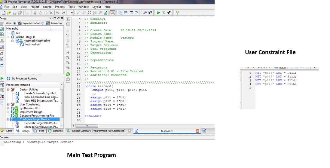
Now, after generating the programming file, select configure target device from the process list and iMPACT will load. To just program the FPGA over JTAG without worrying about the PROM, select Boundary Scan, right click, select Initialize Chain, and if the FPGA is connected it should almost instantly detect it. You’ll then be prompted for a BIT file to program it, or you can right click the symbol for the chip and select a file that way. It’ll also prompt you to ask if you want to generate a PROM file. If you’re just loading the chip once, click no. Right click the symbol, hit program, and it’ll program the FPGA.
Now, if we want to make the program persistent on the FPGA, we need to program the PROM which is only slightly harder. This time, select yes to make a PROM programming file or alternatively select “Create PROM File (PROM File Format…)” from the iMPACT Flows list. This will start the PROM File Formatter:

For More Details: DIY FPGA Programming