1. Introduction: Raspberry Pi Embedded System Development Kit
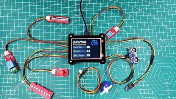
The Raspberry Pi Embedded System Development Kit offers an ideal platform for both learning and utilizing Raspberry Pi capabilities. Built around the Raspberry Pi Zero, it features a 320*240 LCD with touch functionality for display purposes, along with an integrated chip for audio processing, playback, and recording. Additionally, it includes a speaker, a 3.5mm audio jack, and dual microphones, along with standard Pi add-ons like A/D and GPIO expansions. Utilizing an SPI display and hardware expansions such as Mic/Audio, it is tailored to cater to the needs of embedded projects more effectively.
Being among the most prosperous open hardware platforms, Raspberry Pi has found extensive use across numerous applications. This Pi interface Hat serves as an excellent learning tool for beginners keen on exploring Raspberry Pi. Makerfabs has curated a plethora of demos for Raspberry Pi, facilitating effortless learning in displaying, playing, recording, and more. Hence, let’s initiate our journey with the Raspberry Pi Embedded System Development Kit.
2. Features
The Raspberry Pi Zero W features a 1GHz single-core CPU, 512MB of RAM, a Micro USB OTG port, a Mini HDMI port, a CSI camera connector, wireless LAN, and Bluetooth capabilities. It also comes equipped with a 3.2-inch display boasting a resolution of 320×240, driven by the ili9341 driver via SPI. The display features a resistive touch screen with an XPT2046 controller, along with a built-in speaker and a 3.5mm audio jack. It includes a Stereo Codec with a Class D Speaker Driver (WM8960) and MEMS microphones (AOS3729A-T42-NXC). Furthermore, the hardware is expandable with I2C, GPIO, and UART ports, as well as an ADC port supported by the ADS1115. It can be powered via Type-C USB or battery, supporting chargeable operations with a maximum charging current of 1A. Additional safety features include overcharge and over-discharge protection. The dimensions of the device measure 94mm x 80mm x 24mm.
3. Diagram & Parts Details
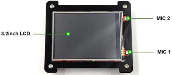
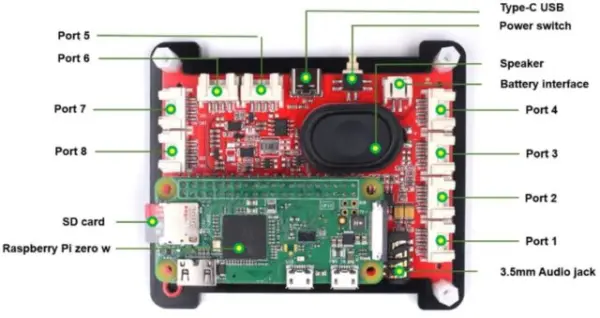
The board features a 3.2-inch TFT LCD Display, accompanied by a pair of microphones on either side.
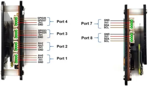
Port1, port2, port3, port4, port7, and port8 are situated on the left and right edges. These ports encompass Power Pins, GPIO Pins, Analog Pins, and I2C Pins.
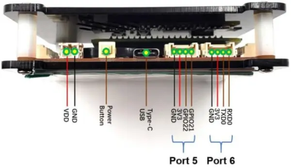
The front side features port5 and port6, serving as Power, GPIO, and UART Pins. To provide power to the board, a Type C USB port is present. Additionally, there’s a power button to activate the module.
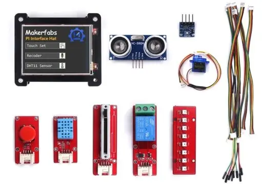
The kit features a Raspberry Pi Zero W Board integrated with a 16GB SD Card Storage. It includes a 3.5mm Audio Jack for audio input and an onboard Speaker for audio output. Power options include a 3.7V Lithium-Ion Battery or a Type C USB Power Supply.
4. Basic Usage
To initiate, begin by unboxing the product package, pressing the button, and subsequently, the Pi interface Hat will be operational. Upon system power-up (Pi Zero necessitates approximately one minute for startup), a brief animation accompanied by audio will be displayed.
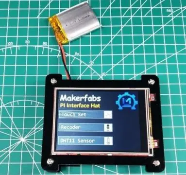
Afterward, you’ll encounter three options displayed for running various programs. Simply press the desired option to initiate the corresponding program. You can then explore some basic demos, including screen testing, audio recording, and temperature measurement.
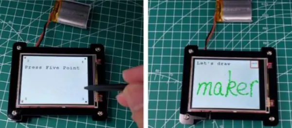
Touch Set
Touch each black pixel on the screen individually using your finger or a touchscreen pen to calibrate the touch accuracy. After each pixel is touched, the screen will flash to a new page where you can freely touch or draw. To return to the options menu, press the button located at the top right corner.
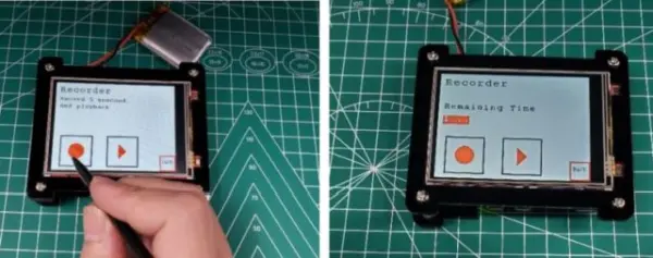
Record audio
Press the recording button on the left to initiate a 5-second audio recording. Then, click the play button on the right to listen to the recorded audio through the speaker.
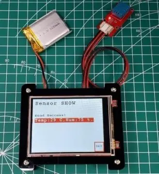
Measure temperature
Attach the Mabee_DHT11 module to Port 5 (GPIO 22) of the device, then press the temperature measurement button. The screen will show the temperature and humidity readings shortly after.
5. Connecting to Internet via WiFi
Prior to beginning, ensure you connect the Raspberry Pi to your WiFi network.
Prepare a Software
SSH, which stands for Secure Shell, is a cryptographic network protocol designed to facilitate the secure operation of network services across unsecured networks. While it is commonly used for remote command-line access, login procedures, and executing commands remotely, SSH can secure any network service.
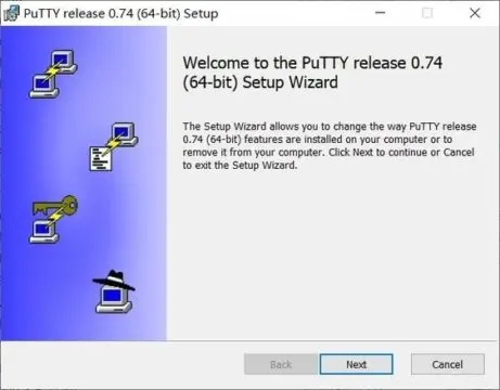
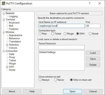
B. PuTTY tool
PuTTY functions as an SSH client, commonly employed for remote Raspberry Pi management. You can obtain the installation package from this link: https://www.putty.org/.
How to connect?
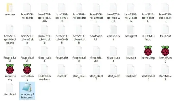
Extract the SD card from the Raspberry Pi and insert it into the PC. Navigate to the SD card’s root directory where you’ll find several files.
In this root directory, generate a new file named “wpa_supplicant.conf”.
Begin by opening a fresh file named wpa_supplicant.conf with a text editor, then paste the provided code snippet below into it. Replace the placeholders “***” with your actual WiFi SSID and password. Finally, save the file and close the editor.
|
1
2
3
4
5
6
7
|
Country=CN
ctrl_interface=DIR=/var/run/wpa_supplicant GROUP=netdev update_config=1
network={
ssid=”*****”
psk=”****”
key_mgmt=WPA–PSK
priority=1
|
Set up a folder called SSH in the root, which is to turn on the Raspberry Pi SSH service.

Insert the SD card back into the Raspberry Pi and re-power the Pi Interface Hat. The Raspberry Pi will then automatically establish a connection to Wi-Fi.
Ensure both your computer and Raspberry Pi are connected to the same network. Launch Putty, input “raspberrypi.local” in the address field, and then click “open”.
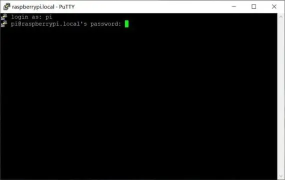
Please provide the Raspberry Pi username and password in sequential steps.
Raspberry Pi Username: pi
Initial Raspberry Pi password: raspberry
Note: The password will not be visible as you enter it, and it must be entered in a single attempt.
Now input the command “ifconfig” in the terminal to check the Raspberry Pi IP.
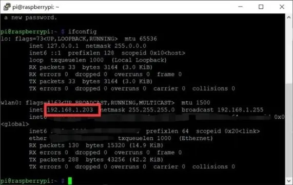
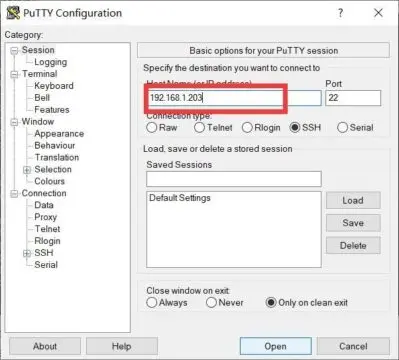
The WiFi connection has been successfully established. Next time, you can utilize the IP address to access the Putty terminal, as outlined below.
6. Kill the process of default program.
Due to the automatic initiation of the default program (the 3 demos), it becomes necessary to terminate the process to prevent the Pi from being occupied. Follow these steps to terminate it:
Execute the “top” command in the terminal and locate the ID of the default program. In the top table, identify the PID (Process ID) number associated with the “default_demo” command. This PID number corresponds to the process that needs to be terminated.
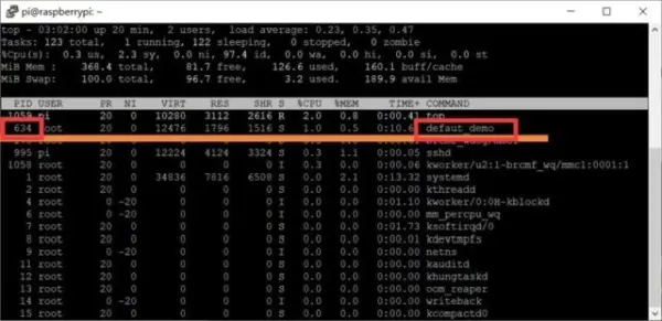
Click “Ctrl+C” to exit the top table.
Enter the below command to kill the process.
|
1
|
Sudo kill 634
|
7. Projects with Raspberry Pi Embedded System Development Kit
To delve deeper into learning, Makerfabs has included various examples demonstrating how to utilize the provided resources. In several instances, supplementary programs are required in addition to Raspberry Pi commands.
For ease of access, we’ve uploaded the project onto the Raspberry Pi, and the subsequent chapter will detail how to utilize these resources effectively. The project encompasses all necessary programs for the demonstration, and it’s imperative to adhere to the steps outlined for successful utilization of the programs.
1. Recode and Play
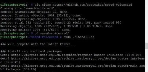
Please proceed with the following instructions to install the Linux kernel drivers for recording and playback. Note: If the Raspberry Pi OS has been provided by Makerfabs, you can skip this step as the drivers are already installed.
(Optional) Enter the following command in the Raspberry Pi terminal window to install the driver:
|
1
2
3
4
|
git clone https://github.com/respeaker/seeed-voicecard
cd seeed–voicecard
sudo ./install.sh
sudo reboot
|
Print the sound card list to see if the driver installation is successful.
|
1
|
Aplay –l
|
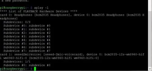
“Card 1” functions as the controller for both the speakers and microphones.
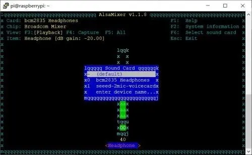
Utilize the “alsamixer” command to access the interface for adjusting the volume of the sound card. Press the F6 key to toggle between different sound cards. In the illustration, “x1” represents your specific sound card.
For voice recording, execute the following command. Upon completion, Raspberry Pi will generate a two-channel WAV file. Occasionally, you may need to adjust the number in the text “-Dhw:1,0” to “-Dhw:0,0”, “-Dhw:2,0”, or another number.
“`bash
arecord -c 2 -r 16000 -f S16_LE -Dhw:1,0 -d 3 temp.wav
“`
In this command, “-Dhw:1,0” specifies the use of sound card 1 for recording, “3” denotes a recording duration of 3 seconds, and “temp.wav” is the designated filename for saving the recording.
To play audio, employ the following command:
“`bash
aplay -Dhw:1,0 temp.wav
“`
Here, “-Dhw:1,0” indicates the utilization of sound card 1 for output, and “temp.wav” represents the filename of the audio output.
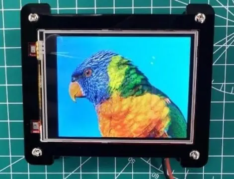
2. Display picture
The board incorporates a 3.2-inch LCD featuring the ILI9341 driver, linked to the Raspberry Pi Zero via SPI rather than the HDMI interface. To make adjustments in the code, navigate to main.c. Remove the “//” preceding “lcd_basic()” to uncomment this function, while adding “//” before the other function to comment it out. This ensures that only the “LCD_basic();” function is executed.
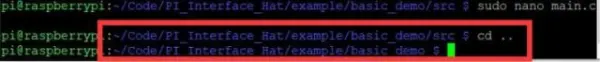
Command:
“`bash
sudo nano main.c
“`

Click “Ctrl+o” and Enter to save, then click “Ctrl+x” to exit.
- Return directory to “/PI_Interface_Hat/example/basic_demo”.
|
1
|
Cd..
|
You can see the current location of the directory in the terminal.
Execute the command to compile the program:
“`bash
make
“`
List all files in the directory to ensure the executable file has been added. Then proceed to execute it:
“`bash
ls
sudo ./basic_demo
“`
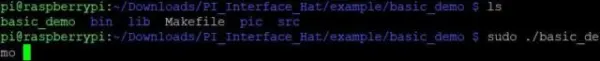
- The picture will be displayed on the screen.
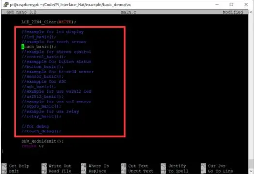
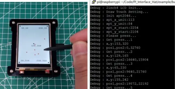
3. Touch screen
The LCD is equipped with a touch panel featuring XPT2046. Following the previous instructions, navigate to the directory “~/Code/PI_Interface_Hat/example/basic_demo/src” and adjust the main.c file to rectify the program’s functionality. As illustrated in the figure, uncomment the line “touch_basic()”.
“`bash
cd ~/Code/PI_Interface_Hat/example/basic_demo/src
sudo nano main.c
“`
Navigate to the directory “~/Code/PI_Interface_Hat/example/basic_demo” and execute the command to compile the program:
“`bash
cd ~/Code/PI_Interface_Hat/example/basic_demo
make
“`
List all files in the directory to confirm the executable file is included, then run it:
“`bash
ls
sudo ./basic_demo
“`
The touch position will be shown in the SSH terminal when interacting with the touchscreen.
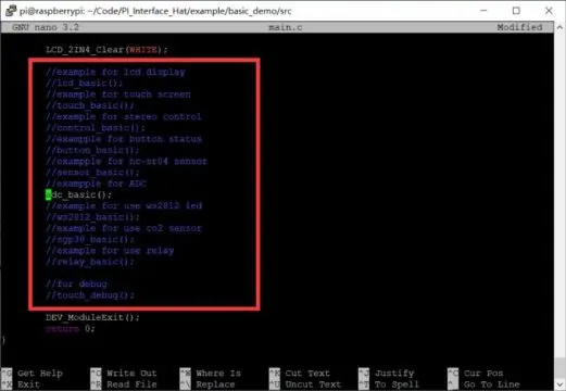
4. Get the ADC value
As you’re aware, Raspberry Pi lacks built-in ADC functionality. However, with the Pi Interface Hat incorporating the ADS1115 chip, it offers four-channel ADC capabilities accessible through Port 1 and Port 2 interfaces. Below, we’ll explore A/D conversion for input voltage signals.
Connect the Potentiometer to Port 1.

- As the above steps to modify and execute the code “main.c”. Uncomment the specified function in the main.c.
|
1
2
|
//exampple for ADC
adc_basic();
|
- Follow the below step to execute the “make” command for verifying the program and run it.
|
1
2
3
|
cd ~/Code/PI_Interface_Hat/example/basic_demo
make
sudo ./basic_demo
|
- The ADC value would be obtained and shown on the LCD.
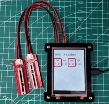
The detail of the code for getting the value from the ADC in the “/PI_Interface_Hat/example/basic_demo/src/adc_basic.c“.
|
1
2
3
4
5
6
7
8
9
10
11
12
13
14
15
16
17
18
19
20
21
|
int handle = wiringPiI2CSetup(ADS1115_ADDRESS);
while (1)
{
float volts[4];
char value_str[80];
for (int i = 0; i < 4; ++i)
{
float v = readVoltage(handle, i, 0);
if (v > 6)
{
v = 0;
}
volts[i] = v;
}
sprintf(value_str, “%4.2lf %4.2lf %4.2lf %4.2lf”, volts[0], volts[1], volts[2], volts[3]); Paint_Clear(WHITE);
Paint_DrawString_EN(10, 110, value_str, &Font16, WHITE, BLACK);
LCD_2IN4_img(10, 110, 240, 130, (UBYTE *)BlackImage);
}
|
Display the value on the LCD.
|
1
2
|
Paint_Clear(WHITE);
Paint_DrawString_EN(10, 110, value_str, &Font16, WHITE, BLACK);
|
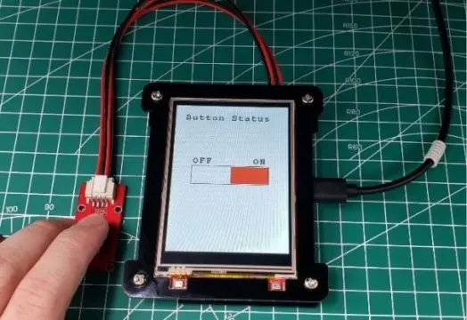
- Connect the BOTTON to the Port 4, that the signal wire is connected to GPIO26.
To implement the modifications and execute “main.c” as outlined above, uncomment the content within the “main.c” file.
“`c
// Example for button status
button_basic();
“`
Proceed with the following commands to execute the “make” process step by step:
“`bash
cd ~/Code/PI_Interface_Hat/example/basic_demo
make
sudo ./basic_demo
“`
- The demo code which read the value of button is “/PI_Interface_Hat/example/basic_demo/src/button_basic.c“. Get the value of the button:
|
1
2
|
int button_pin = 12;//GPIO 26
DEV_GPIO_Mode(button_pin, INPUT);
|
Display the button status on the LCD.
|
1
2
3
4
5
6
7
8
9
10
11
|
if (DEV_Digital_Read(button_pin) == LOW)
{
LCD_2IN4_FillRect(121, 141, 199, 178, WHITE);
LCD_2IN4_FillRect(41, 141, 120, 178, BLACK);
}
else
{
LCD_2IN4_FillRect(41, 141, 120, 178, WHITE);
LCD_2IN4_FillRect(121, 141, 199, 178, RED);
}
DEV_Delay_ms(100);
|
6. Get the CO2 level
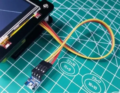
The Pi Interface Hat offers two I2C interfaces, designated as Port 7 and Port 8. Attach the SGP30 sensor to Port 7, and refer to the following diagram for the sensor’s connection details.
(If needed) Execute the command to install the SGP30 library for driving. However, if you’re using Makerfabs’ default OS in the Hat SD card, this step is unnecessary as it’s pre-installed.
“`bash
sudo pip3 install pimoroni-sgp30
“`
(Optional) Also, install the package required to support the SGP30 library.
“`bash
sudo pip3 install smbus2
“`
After completing the above steps, proceed to modify the “main.c” code. Uncomment the content related to the SGP30 in the “main.c” file.
“`c
// example for use CO2 sensor
sgp30_basic();
“`
Follow the steps below to execute the “make” command.
“`bash
cd ..
make
sudo ./basic_demo
“`
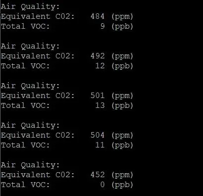
The obtained values will be displayed in the Raspberry terminal.
- The demo code for SGP30 to monitor is “/PI_Interface_Hat/example/basic_demo/py/sgp30_test.py” and is different from others. It was done in Python and would be run by Linux command.
Run the Linux command in /PI_Interface_Hat/example/basic_demo/src/sgp30_basic.c.
|
1
|
system(“sudo python3 ./py/sgp30_test.py”);
|
Initialize the SGP30 sensor in the python file /PI_Interface_Hat/example/basic_demo/py/sgp30_test.py.
|
1
2
|
sgp30 = SGP30()
sgp30.start_measurement(crude_progress_bar)
|
Get the CO2 level.
|
1
2
3
|
result = sgp30.get_air_quality()
print(result)
time.sleep(1.0)
|
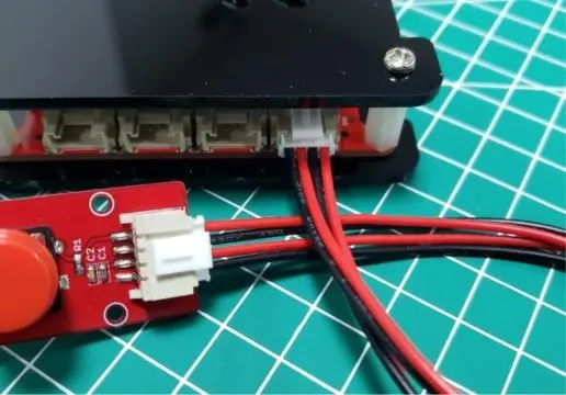
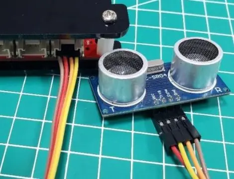
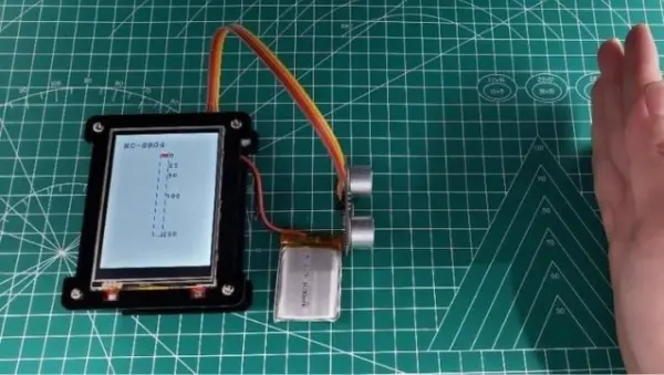
7. Use HC-SR04 to measure the distance
Attach the HC-SR04 module to Port 4, referring to the connection diagram illustrated in the following figure.
- As the above steps to modify and execute the code. Modify the code that uncomment special content in the main.c.
|
1
2
|
//exampple for hc-sr04 sensor
sensor_basic();
|
- Follow the above tutorial to run the “make” command and execute the program.
- The detail of measuring the distance in the /PI_Interface_Hat/example/basic_demo/src/sensor_basic.c
|
1
2
3
4
5
6
7
8
9
10
11
12
13
14
15
16
17
18
19
20
21
22
23
24
25
26
|
unsigned int begin_time = micros();
// Wait for ping response, or timeout.
while (digitalRead(ECHO) == LOW && micros() – begin_time < timeout)
{
}
// Cancel on timeout.
if (micros() – begin_time > timeout)
{
printf(“1.Out of range.\n”);
return 0;
}
ping = micros();
// Wait for pong response, or timeout.
while (digitalRead(ECHO) == HIGH && micros() – ping < timeout)
{
//printf(“ECHO HIGH\n”);
}
// Cancel on timeout.
if (micros() – ping > timeout)
{
printf(“2.Out of range.\n”);
return 0;
}
pong = micros();
// Convert ping duration to distance. distance = (int)((pong – ping) * 0.017150); printf(“Distance: %.d cm.\n”, distance);
|
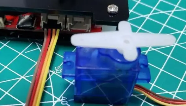
8. Control the servo
The mini servo consists of three pins: red for VCC, brown for GND, and yellow for signal. It operates through PWM signal control. Connect the servo’s signal pin to Port 5 (GPIO21 in hardware).
Please follow the instructions above to uncomment the content in the “main.c” file of the project.
“`c
// example for stereo control
control_basic();
“`
To ensure successful servo operation, it’s essential to verify the signal pin used in the code located at “/src/control_basic.c”. Utilize the following command to open the “control_basic.c” code.
“`bash
sudo nano control_basic.c
“`
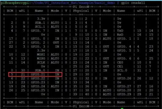
Note: To change the port code to 5, as specified in the BCM2835 library, which is a C library for Raspberry Pi providing access to GPIO and other IO functions on the Broadcom BCM 2835 chip, GPIO21 is represented as “5” in the BCM:
|
……
servo_init(5);
servo_angle(5, 0);
……
servo_angle(5, angle);
|
Click “Ctrl+o” and Enter to save then click “Ctrl+x” to exit.
- Follow the below steps to run the “make” command for verify the program.
|
1
2
3
|
cd ~/Code/PI_Interface_Hat/example/basic_demo
make
sudo ./basic_demo
|
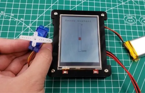
- The control button will be displayed on the LCD. Touch the screen to drive the servo running.
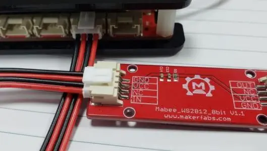
9. Control the WS2812 LEDs
Link the WS2812 LEDs to Port 3, with the signal pin controlling them connected to IO23.
- (Optional) There is no library that support WS2812 and you have to run the command to install the WS2812 library.
|
1
|
sudo pip install rpi_ws281x
|
- Uncomment the content in the main.c of the project.
|
1
2
|
//example for use ws2812 led
ws2812_basic();
|
- Open “ws2812_basic.c” by:
|
1
|
sudo nano ws2812_basic.c
|
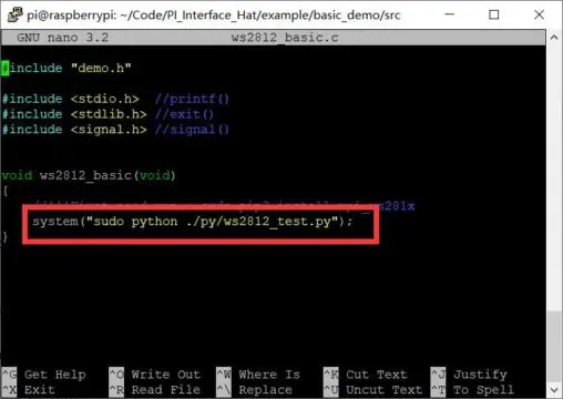
Modify the code to “sudo python ./py/ws2812_test.py”, the final such as the picture.
- Follow the steps to verify the program and execute it.
|
1
2
3
|
cd ~/Code/ PI_Interface_Hat/example/basic_demo
make
sudo ./basic_demo
|
- The demo code for WS2812 is /basic_demo/py/ws2812_test.py. The LED configuration:
|
1
2
3
4
5
6
7
8
|
# LED strip configuration:
LED_COUNT = 12 # Number of LED pixels.
LED_FREQ_HZ = 800000 # LED signal frequency in hertz (usually 800khz)
LED_DMA = 10 # DMA channel to use for generating signal (try 10)
LED_BRIGHTNESS = 50 # Set to 0 for darkest and 255 for brightest
# True to invert the signal (when using NPN transistor level shift) LED_INVERT = False
LED_CHANNEL = 1 # set to ‘1’ for GPIOs 13, 19, 41, 45 or 53 LED_PIN = 13 # BCM13 / GPIO23
|
Initialize the ws2812:
|
1
2
3
|
strip = Adafruit_NeoPixel(LED_COUNT, LED_PIN, LED_FREQ_HZ,
LED_DMA, LED_INVERT, LED_BRIGHTNESS, LED_CHANNEL)
strip.begin()
|
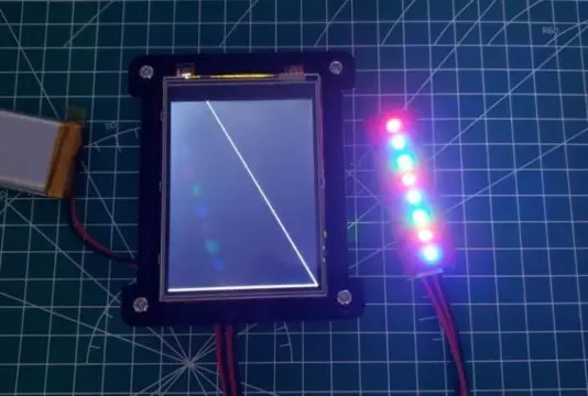
Turn the LED on:
|
1
2
3
|
for x in range(0, LED_COUNT):
strip.setPixelColor(x, Color(255, 0, 0))
strip.show()
|
Here’s a guide to kickstart your journey with the Raspberry Pi Embedded System Development Kit tailored for beginners. Beyond the introductory projects, the possibilities are virtually limitless, with thousands of potential projects waiting to be explored using this comprehensive kit.