Raspberry Pi Camera Interface
The Raspberry Pi’s CSI camera connectors come in two distinct formats – the 15-pin and 22-pin connectors. The 15-pin variant is typically found on standard Raspberry Pi models such as the A&B series, as well as on dedicated camera modules. In contrast, the 22-pin connector is specifically used by the Raspberry Pi Zero-W and Compute Module IO Board. Moreover, Arducam has developed modified versions of these connectors, catering to various camera board designs, which may employ different FPC (Flexible Printed Circuit) contact positions, offering increased versatility.
15-Pin Connector
The 15-pin connector is the de facto standard for Raspberry Pi cameras, being the default connector in most instances. It’s prominently featured in numerous Raspberry Pi products, including the Model A&B series, as well as the V1 and V2 camera modules, which are widely popular among users.
In the realm of Pi-camera-related hardware, it’s not uncommon to stumble upon at least three distinct iterations of the 15-pin connector, each with its own characteristics and nuances.
Connector on the V1.3 or V2.1 Pi Camera Board.
This connector is a type of 1.0mm pitch FFC/FPC, characterized by its 15-pin configuration, right-angle design, and lower contact.
Connector PN: SFW15R-2STE1LF
Connector on the Raspberry Pi Model A, B or B Plus.
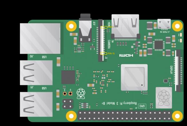
Specifically, this connector employs a 15-position vertical surface-mount FFC/FPC configuration, boasting a 1.0mm pin pitch.
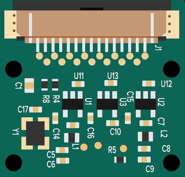
Derived or Alternative Connectors on Arducam Raspberry Pi Camera Products.
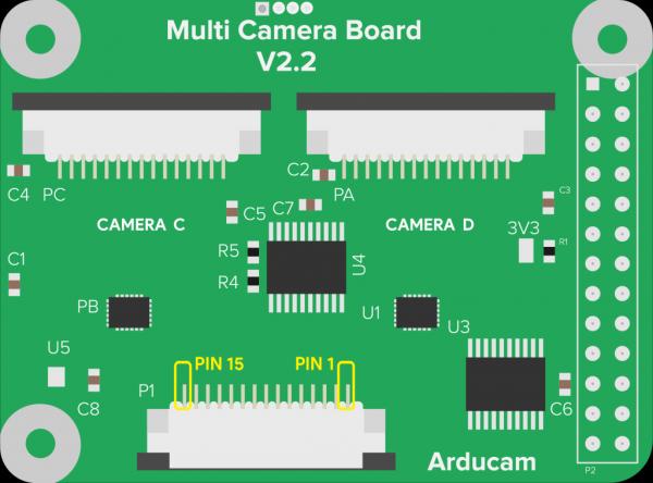
Furthermore, Arducam has introduced a modified 15-pin connector design with an additional upper contact point. This adaptation features the FPC (Flexible Printed Circuit) contact component shifted to the upper side of the connector, deviating from the conventional camera board-based layout.
Regardless of the specific connector type, the pinout configuration remains uniform across these camera connectors. A table detailing the pin definitions for the camera board is provided, indicating whether each signal is an input or output. Conversely, these same pins on the Raspberry Pi (RPI) board operate in the opposite direction, with input signals being output and vice versa.
Raspberry Pi Camera Pinout (15-Pin)
| Pin # | Name | Description |
|---|---|---|
| 1 | GND | Ground |
| 2 | CAM_D0_N | MIPI Data Lane 0 Negative |
| 3 | CAM_D0_P | MIPI Data Lane 0 Positive |
| 4 | GND | Ground |
| 5 | CAM_D1_N | MIPI Data Lane 1 Negative |
| 6 | CAM_D1_P | MIPI Data Lane 1 Positive |
| 7 | GND | Ground |
| 8 | CAM_CK_N | MIPI Clock Lane Negative |
| 9 | CAM_CK_P | MIPI Clock Lane Positive |
| 10 | GND | Ground |
| 11 | CAM_IO0 | Power Enable |
| 12 | CAM_IO1 | LED Indicator |
| 13 | CAM_SCL | I2C SCL |
| 14 | CAM_SDA | I2C SDA |
| 15 | CAM_3V3 | 3.3V Power Input |
22-Pin Connector Types
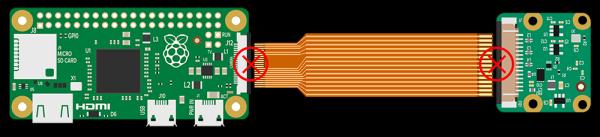
Connector on the Raspberry Pi Zero W.

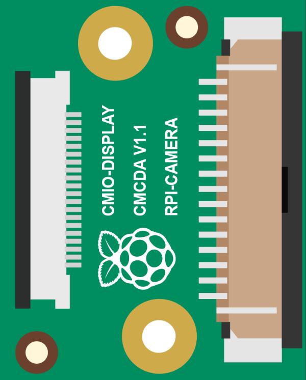
Connector on the Raspberry Pi Compute Module IO Board.
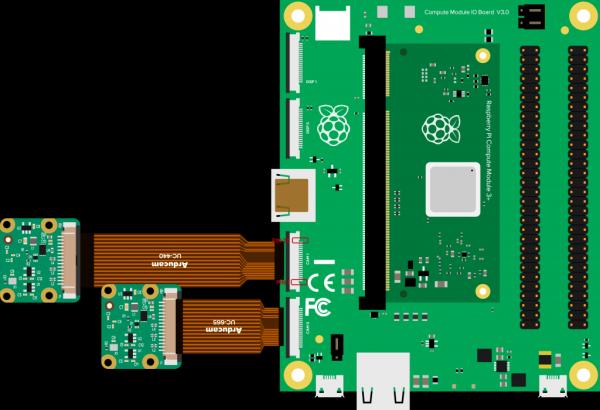
It is 0.5mm fine pitch 22-position lower (or bottom) contact FFC or FPC connector.
The following table is the pin definition on the Pi ZERO-W or Compute Module IO Board.
Raspberry Pi Camera Pinout (22-Pin)
| Pin # | Name | Type | Description |
|---|---|---|---|
| 1 | GND | Ground | Power Ground |
| 2 | CAM_D0_N | Output | Pixel Data Lane0 Negative |
| 3 | CAM_D0_P | Output | Pixel Data Lane0 Positive |
| 4 | GND | Ground | Power Ground |
| 5 | CAM_D1_N | Output | Pixel Data Lane1 Negative |
| 6 | CAM_D1_P | Output | Pixel Data Lane1Positive |
| 7 | GND | Ground | Power Ground |
| 8 | CAM_CK_N | Output | Pixel Clock Output Form Sensor Negaitive |
| 9 | CAM_CK_P | Output | Pixel Clock Output Form Sensor Positive |
| 10 | GND | Ground | Power Ground |
| 11 | CAM_D2_N | Output | Pixel Data Lane2 Negative |
| 12 | CAM_D2_P | Output | Pixel Data Lane2 Positive |
| 13 | GND | Ground | Power Ground |
| 14 | CAM_D3_N | Output | Pixel Data Lane3 Negative |
| 15 | CAM_D3_P | Output | Pixel Data Lane3 Positive |
| 16 | GND | Ground | Power Ground |
| 17 | POWER-EN | Input | Power Enable |
| 18 | LED-EN | I/O | LED Enable/XCLK |
| 19 | GND | Ground | Power Ground |
| 20 | SCL | Input | SCCB serial interface clock input |
| 21 | SDA | I/O | SCCB serial interface data I/O |
| 22 | VCC | Power | 3.3V Power Supply |
15 to 22 Pin FPC Adapter Schematic
Here is an alternative wording for the given passage:
The diagram below illustrates the pin mapping transformation from the 15-pin layout to the 22-pin layout. It’s essential to recognize that certain pins within the 22-pin configuration are not activated or utilized in this specific implementation.
Interestingly, the schematic design of the compute module camera adapter board is actually based on the pin mapping diagram presented earlier.
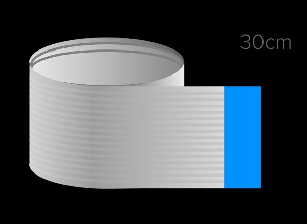
Various FPC Cable Lengths
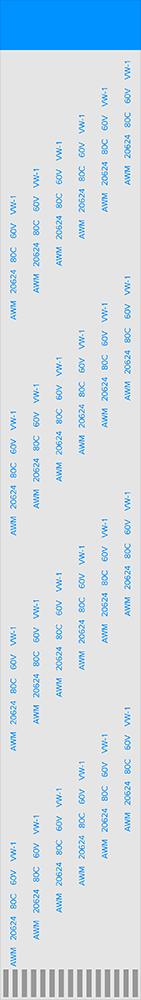
The default Pi Camera cable
The default Raspberry Pi Camera FPC cable is 15 cm long, opposite the side contactor.
To cater to a broad range of applications, Arducam offers a diverse range of Raspberry Pi camera cables. While their standard offerings may meet the needs of most users, there may be situations where longer or shorter cables are essential. To address these requirements, Arducam provides a wide variety of cable options, ensuring that users can find the perfect solution for their specific needs.
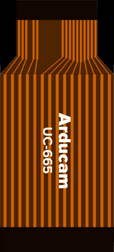
Arducam Camera Cable for Raspberry Pi (15-pin).
Arducam Camera Cable for Raspberry Pi (15-to-22-pin)
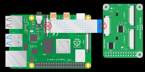
Troubleshooting
We’ve prepared a visual representation highlighting incorrect methods of connecting the camera cable. To resolve any issues or concerns while utilizing the camera, it is paramount that these methods are not attempted. Please strictly adhere to the correct protocols to ensure proper camera function.