Continued
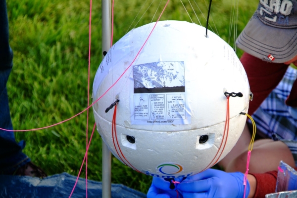
Part one of this series of articles on Team Near Space Circus flight NSC-01 can be found >here<. It covered the physical layout of the 7 Raspberry Pis, 8 cameras and power system. It left off as we were about to go into the details of the network topology itself.
Plan A: 2 Pi in a Pod…
The initial plan was for 2 Raspberry Pi using a serial communication protocol. The Model A+ does not have an ethernet port. Of course a Raspberry Pi 2 has one, and is more powerful, but it also consumes a lot more power than the A+. Our battery pack would have had to be much larger if we went down that path, and that meant significantly heavier. We had a goal of 2Kg for the payload itself, and we were getting close, so serial it was..
Serial communication
Many early personal computers typically had two interfaces, either built in or available through an expansion card: a serial (either a DB9 or DB25 connector) and a parallel interface (either a DB25 or 36 pins Centronics connector, aka IEE1824). The parallel interface was typically used for printers (and great for DIY DACs with resistor ladders, but that’s a story for another time), while the serial port was mostly used for modems or scientific equipment.
 RS-232 was introduced in 1962, so it’s been around for quite a while now. Many serial connections were actually TTL (5V), such as on the Digital Decwriter III, but it was quite easy to convert them to a +/- voltage range (and even more so since the mid 80s with ICs such as the MAX232). The initial purpose was to connect a DTE (Data Terminal Equipment), a fancy way of saying a computer, and a DCE (Data Communication or Circuit-terminating Equipment).
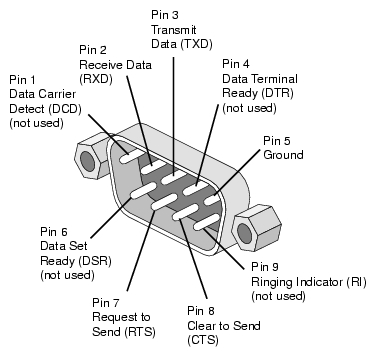
On a DB9 connector, the pins would be (DB9 male connector pictured):
RxD is Receive Data and TxD is Transmit Data. What if you need to connect two DTE together? You need a Null-Modem adapter or cable. The simplest Null-Modem circuit requires 3 wires (2 if you can guarantee the ground on each end to be the same)
Raspberry Pi Header
The Raspberry Pi doesn’t have a DB9 or DB25 connector. But if you look at the 40 pin header, notice on the top row, the 4th and 5th pins.
TXD and RXD. It is a serial port, but it is *not* RS-232 compatible as far as voltage levels are concerned (a 1 is marked by a negative voltage in the range -3V to -15V, and a 0 by a positive voltage in the range +3V to +15V), as it is a TTL interface (a 1 is marked by a positive voltage, either 3V3 or 5V and a 0 is marked by 0V). But that is fine, we are only connecting to another Raspberry Pi.
The primary issue with this serial port is that the Raspbian operating system has a console (TTY) associated it. Meaning that you could connect this to a computer, with the right cable, and see the boot process and get a console prompt, and be able to type commands, as if you had a keyboard and monitor connected directly to the Raspberry Pi.
In our case, however, we want to use the port for something else, our own communication network, so we have to disable this feature. It was once a manual process, and I had written a script to do it, but…
Configuration
Once we have reconfigured the serial port, we can quit raspi-config and reboot. For each compute node, beside disabling the serial port console, we also enabled on the advanced page the SPI and I2C options, and on the main page we configured the time zone, enabled the camera and expanded the filesystem. We also overclocked nodes 1-3 to 800 MHz while nodes 4-6 ran at 700 MHz (so we can measure the impact of overclocking).
Plan B: A Pi cluster
By using a pair of Raspberry Pi, the communication process is pretty straightforward. With two nodes, we can use SLIP or Point to Point Protocol (PPP). Initially, this was the thought for NSC-01 and we would not have to write the code for the network layer.
But without a functioning camera switcher, the only option was to use one node per camera (each Raspberry Pi has 1 CSI camera connector, even thought the Broadcom chip supports 2 – most cell phones have a front and rear camera). With 7 CSI cameras in total, that meant 7 Raspberry Pi.
Time to dig in our bag of tricks…
Token Ring
As I was going through the options, I started thinking about good old IBM Token Ring (and FDDI). Conceptually, at least. I wasn’t going to make something compatible with 802.5, but instead reuse the concept with the serial UART, transmit to receive from one node to the next.
Conceptually, a node is always listening to the serial port. Is this data for me? (if it’s a broadcast or if it’s addressed to me) If not or if a broadcast, I send it right away to the next node, and process it if it is addressed to me. So let’s get into the details.
The diagram
In the previous article, one of the pictures clearly showed 7 Raspberry Pi connected together inside the payload. I’ve included here a fritzing diagram to help in detailing what is going on here.
In the diagram above, I didn’t have a Raspberry Pi model A+ for fritzing, so I used the closest thing for our purpose, a Raspberry Pi model B+. Both of them have a 40 pins GPIO header. First row at the top, from left to right has 5V, 5V, GND, TxD and RxD. We’ll stop there for right now.
Here I’ve simply connected node 1 TxD to node 2 RxD (blue wire), node 2 TxD to node 3 RxD (pink), node 3 TxD to node 4 RxD (brown), node 4 TxD to node 5 RxD (cyan), node 5 TxD to node 6 RxD (orange), node 6 TxD to node 7 RxD (yellow) and finally node 7 TxD to node 1 RxD (green), in a nice circular (or ring) fashion.
 The GND are not daisy chained from one Pi to the next, because they are all powered by the same source, through their microusb plugs.
Initially, I tried to power the Pi directly from the 5V pin on the GPIO header, but the signal was decoding only partly. By further connecting the 3.3V (that was key, the UART operates at 3V3 so the HIGH signal was not detected reliably when powered with only 5V) and GND together, it made it more reliable, but also more complicated. I reverted back to powering all the 7 nodes using microusb (as detailed in the previous article).
Python
What’s great about Raspbian is that not only do we have Python installed, but Python 2.x and 3.x are there, along with many things that are normally optional, such as pygame, pyserial, RPi.GPIO etc. Batteries are quite definitely included with Python on the Raspberry Pi.
Still, for the networking software, we did install two modules from pypi using pip3 (we are using Python 3), docopt and sh.
For the bulk of the development, I used a Raspberry Pi Model B+ connected to my laptop and to a second Raspberry Pi using the serial port and the network switch. That way my laptop could see both Raspberry Pi and I could push new versions of the software using scp.
For more detail: The computer network in space – Part 2