I’ve had a Raspberry Pi since Christmas, but haven’t done much with it up till now. That’s all changed since I moved house. Getting to grips with a new central heating system, I find that (for reasons too dull to list here) I need to monitor and control it rather more flexibly than I can do with the standard timer. I also don’t want to pay lots of money for a Nest controller, however beautiful it may expect itself to be considered. My first thought was to use an Arduino – the problem I’m addressing does not need a lot of processing power, and I don’t want to spend a lot – but I came up against a problem which seems to me to be the Arduino’s biggest failing at the moment. I want to be able to control the system over WiFi. There are WiFi shields for Arduino, of course, but they start at £30, twice the price of the Arduino.
The hardware requirements of the system I want to build are quite simple. It must monitor two or more temperature sensors, and it must be able to control two or three relays capable of switching mains voltage. Having a couple of controllable status LEDs would be good, too. I don’t require any other user interface input or display in hardware, because I want to use a web interface. The Pi is more than capable of handling all this, but it turns out that there is quite a bit of software installation and configuration to do. All of it can be done over a ssh connection (I use PUTTY for this), which is fortunate because I don’t actually have a monitor with an HDMI input that I can use as a display for the Pi.
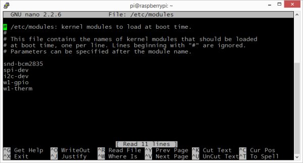
The temperature sensors I am using are DS120B types. Rather than being dumb devices like thermistors (whose resistance varies with temperature) they have logic inside which allows them to communicate with a host over a three wire digital serial connection. The manufacturer calls this ‘1-wire’, because the actual communication only needs one, but you also need power and ground, so really there are three). This has several benefits: it means that many devices can share the same wire (as each has its own address), it reduces the likelihood of inaccurate readings caused by long wires, and it means that the host does not need an analogue to digital converter to read them. It also means that the host must implement the 3-wire protocol in order to read the sensors. Fortunately, cleverer people than I have already done the hard work, and there are Linux drivers for these and other three-wire devices. The relevant ones are already present in the raspbian distro, and simply need enabling. Simply? Did I say simply? This is Linux – nothing is simple until you know the magic incantations. I need Linux to load the appropriate 1-wire driver modules when it boots up, so it’s necessary to edit the /etc/modules file, which contains the list of drivers to be loaded. It’s necessary to have root privileges to edit this file:
sudo nano /etc/modules
The lines w1-gpio and w1-therm tell the system to load the one-wire driver for the pi’s GPIO port (GPIO4 is used for this) and also the drier for the DS18B20 chip.
modprobe wire
modprobe w1_gpio
modprobe w1_therm
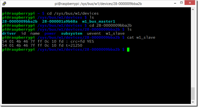
Once these modules are loaded, the system will probe in the background to see if there are any sensors it recognises on the wire. It will then create a new folder for each one under /sys/bus/w1/devices, and pop the data it retrieves from each in a file in there. Reading the temperatures is a simple as reading the values in these files. For example, as I write I have two sensors.on my Pi. If I look in the devices folder, this is what I get:
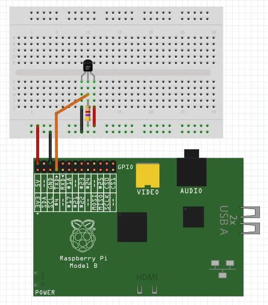
The long number ‘28-0000009bba2b’ is the unique id of the sensor (hard-coded into the sensor itself). The 1-wire driver identifies these and creates links to each. By browsing to the folder and looking at the ‘w1_slave’ file within, the temperature is revealed. it’s the bit saying ‘t=21250’, which is 1000 times the temperature in degrees Celsius (21.25 degrees). If you want the temperature in Fahrenheit, I suggest you go back to the eighteenth century. If you are actually executing the commands, you may notice a short delay between the ‘cat’ and the output. That’s because when you read the file, the system actually contacts the sensor and takes a reading. This is perhaps slower than you might expect, but it’s fast enough for my purposes. For completion, here’s a quick wiring diagram of how to connect up the senor to the pi. the only other component needed is a 4k7 resistor, to tie the communication wire to the 5V line.
The next step is to use python to read these temperatures and store them in a database, then get a web-based interface up to control the relays. I’ll also need to make sure that everything runs automatically, with no user intervention. Watch this space. Unless you have better things to do, which I fervently hope is the case.
Source: Warming to the Pi and Python

