
Section I. Introduction
Dr. Vigil-Haye’s problem is the lack of hardware to demonstrate networking architectures. Dr.
Vigil-Hayes desired the creation of a modular wireless testbed that can be used to represent
different and unique network architectures for her teachings. Each device would allow for an
array of antennas that could connect the different devices throughout the mesh network. These
are inherently modular due to their ability to adjust the usage of different types of antennas
which can be removed or replaced at any time during the demonstration. The main goal of this
project has been to not only implement the technologies desired, but to make the device both
easy to use and to understand. This is primarily because of its educational nature and
complicated subject material.
This user manual is intended to increase the ease of use for this device. Throughout this manual
various aspects of use will be covered. As mentioned in the previous table of contents, these
aspects include installation, configuration and use, maintenance, and troubleshooting. These
sections are provided in hopes to resolve any issues which may arise through the duration of the
device’s lifespan of use.
At the end of this manual is an appendix which includes all necessary data and documented
information needed to rebuild the device successfully. This appendix contains figures used
throughout this manual, documented data sheets applicable to the device, and links to modules
used.
Section II. Installation
Hardware:
All included antennas and hardware comes pre-installed. Specifications on removal and
reinstallation of these parts will be covered in the maintenance section of this manual (see page
8). All ports on the Raspberry Pi 3B+ are exposed through openings in the protective casing,
including four USB ports, ethernet and HDMI ports, 3.5mm auxiliary jack, and Mirco-SD card
slot for data storage.
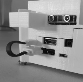
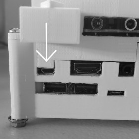
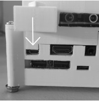
To allow for portability, the built in power source utilizes a short USB to Micro-USB cable. For
portable use, if not plugged in, this cable is to be plugged into the Raspberry Pi’s Micro-USB
power input and the USB port directly below it (Figure 1). This cable can be easily removed for
non-portable or laptop computer use with the Raspberry Pi’s Micro-USB port (Figure 2).
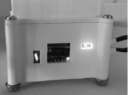
To power on the Raspberry Pi while portable, the integrated power source has a power switch
directly below the Micro-SD slot. When in the ON position, the integrated power source will
display a green LED on the same side of the switch. Consequently, the Raspberry Pi will display
power with a red LED and usage with a green LED through a hole on the same side of the
protective case. On the OFF side of the switch, through a different hole on the same side in the
protective case, the integrated power source displays the level of charge stored within the battery
through four green LEDs, the furthest of which indicates near full charge. Figure 3 displays all
LEDs in operation as well as the power source switch.
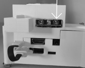
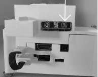
The FM antenna module has two ports; one for speaker output, one for antenna input. The
antenna input is closest to the Raspberry Pi’s USB ports. If not plugged in, the antenna’s 3.5mm
plug is inserted into the port on the module (Figure 4). The LoRa antenna module can be plugged
utilizes a USB plug and can be plugged into the Raspberry Pi’s USB ports.
Software:
Our device were run from a lightweight version of Linux, Raspbian which was installed easily
through NOOBS. The following programs and resources are necessary for the operation of the
Wireless Modular Testbed as we have laid out in previous sections:
● Pip3 for Python
○ Pybluez
○ Pyqt
○ Xbee (for Zigbee applications)
● Wireless Modular Testbed Github code
To install Pip3 along with the rest of the code in Appendix B. Once this is installed the modules
listed will be required to access the correct Python libraries. Once Pip is installed you can install
module from the terminal using:
sudo pip3 install Once all the modules are installed you will want to download the files from the github linked below or from the terminal with: git clone https://github.com/jg2562/WirelessModularTestbed.git Further documentation available here. See Section III for Configuration and Use as well as how to run initial programs.
Section III. Configuration and Use
All hardware come preconfigured for the Testbed and its intended uses, no user action is required
for Raspberry Pi setup outside of power and software. See Appendix B for more information
about the specific hardware used in the project.
Once the software has been installed any program can be used in tandem with the network
program. To run the network from the terminal first navigate to the root folder of
WirelessModularTestbed and run:
python3 network.py
Once the network is running different antenna types will be specified in the program and
parameters will be through the network to the antenna files. Examples of how to run different
servers and clients with wifi and bluetooth antennas are under:
/WirelessModularTestbed/test
For further documentation see the github website:
https://jg2562.github.io/WirelessModularTestbed/
Section IV. Maintenance
Hardware:
For hardware maintenance on the Testbed, the protective casing must be removed. In each corner
of the case is a bolt and nut retaining combination. Remove these screws to allow the top cover
of the protective case to be removed. Before the Testbed may be removed from the protective
casing, the Micro-SD card must be removed from the slot on the Raspberry Pi as well as the
power cable. To keep the integrity of the Zigbee antenna module, the top cover of the case must
be removed in the direction of the extruded arrow on the cover (Figure 5). Once this cover, the
Micro-SD card and power cable are removed, the Testbed may be removed from the case.
With the Testbed removed from the casing, maintenance may be performed on any hardware
attached to the Raspberry Pi. Both the WiFi and Bluetooth antennas are built into the Raspberry
Pi. If these antennas require maintenance outside of software, replacement of the Raspberry Pi
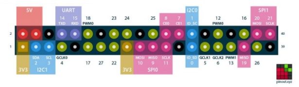
3B+ is recommended, refer to the Appendix B. Both the Zigbee and FM antenna modules utilize
the Raspberry Pi’s GPIO pins (Figure 6). The Zigbee antenna module must be connected to the
first twelve pins on the board. The FM antenna module must be connected to pins three through
six. The LoRa antenna module utilizes a USB plug. If antenna modules are not operating
properly, replacement is recommended (see Appendix B).
All hardware, aside from external antenna modules, is held together with retaining screws to the
Raspberry Pi. Remove these screws in order to separate the three major boards of the Testbed.
The top board of the Testbed is a pin expansion board. This board allows both Zigbee and FM
antennas to use the same pins for proper operation. This board’s input sockets must align with
the pins of the Raspberry Pi. With proper contact to all pins, this board will function as intended.
If board is not operating properly, replacement is recommended (see Appendix B). The
Raspberry Pi 3B+ is the next board down. With the data storage fully inserted into the Raspberry
Pi’s Micro-SD card slot, the Raspberry Pi should work properly. If this is not the case,
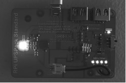
replacement of the Raspberry Pi 3B+ is recommended (see Appendix B). The last board of the
Testbed is the power supply. Check to ensure the power switch is in ON position. This should
illuminate the green power LED on the board as well as at least one of the charge level LEDs. If
the charge level is not indicated by one or more green LED, the power supply needs recharging.
This can be done with any 5V power source with a Micro-USB cable. Plug the power source into
the Micro-USB on the board. If the board is receiving power, a red LED charge indicator will
begin to blink, on and off (Figure 7). If this is not the case, replacement of the battery is
recommended (see Appendix B).

Software:
Check to make sure all software and operating systems are updated to the most recent versions
available. This can be done directly from the terminal using:
sudo pip install [package_name] –upgrade
Section V. Troubleshooting Operation
Hardware:
For hardware troubleshooting, check power and connections. For most trouble-shooting, refer to
the maintenance section of this manual (see page 8). As most modules and antennas are fairly
securely connected, this should not cause much trouble. If all maintenance techniques fail,
replacement of the Raspberry Pi 3B+ module may be necessary, refer to the Raspberry Pi
website labelled in Appendix B.
Software:
Many potential errors arise in implementing new antenna types in the tests. If this is the case make sure to check that the correct parameters are being passed to the antenna file through the network. Some antennas require specific addresses while other will broadcast openly and look for a signal. If you are implementing a new antenna type keep that in mind otherwise use the examples as a reference for how to correctly pass parameters. If pip3 install is not working and giving an OpenSSL.SSL.Error message a common workaround can be used. This is not a fix and does not work for all python packages but most of the common ones. sudo pip3 install –trusted-host pypi.org –trusted-host files.pythonhosted.org
Section VI. Conclusion
Dr.Vigil-Hayes desired the creation of modular wireless testbed that can represent different and
unique network architecture for her teachings. Our delivered device reaches the requirements
that each device allows for an array of antennas that connect with different devices through a
mesh network. The product because of its expandability allows for future growth in the
expansion of other antennas. The modularity of the product further expands on this as antennas
can be removed or replaced at any time. As the team has handed over the code for the network
configuration, this allows for the product to be easily reproduced to create a larger network.
This user manual is intended to allow for the product to be more easily accessible for others.
Whether this in installation, general use, configuration, maintenance, or troubleshooting
operations. The team hopes that the information provided will be beneficial and informative for
the products years in use and resolve any issues that arise.
Finally, the team would like to thank Dr.Vigil-Hayes for sponsoring this project. The team
wishes the best over the course of demonstrating network architecture with the testbed. While the
team is all moving on in our professional careers, we would be happy to answer any questions in
the coming months to help you get the product deployed and operating.
Best wishes from the Modular Wireless Testbed Capstone product developers,
Hannah Caldwell-Meurer, Ryan Hitt, Jack Garrard, Cody Roberts
Section VII. Appendix
Appendix A: Figures


Source: Wireless Modular Testbed