
This little helper can autonomously search for objects you specify based on their unique RGB color patterns. It then navigates its environment, closing the distance until it reaches a designated stop point, just 10 centimeters from the target. But that's not all! While on its mission, the robot expertly avoids any obstacles in its path, ensuring a smooth and successful journey. The brains behind this operation is a powerful Raspberry Pi unit. This compact computer acts as the robot's central processing unit, receiving information from two key sources: A Pi Camera: This camera captures visual data of the environment, allowing the robot to identify objects based on their RGB color patterns. Four Ultrasonic Sensors: These sensors act like robotic eyes, constantly scanning for obstacles in all directions.
Introduction
FindBot represents the next step forward in developing capable yet affordable service robots. Powered by a Raspberry Pi 2 single-board computer, this small-but-mighty machine demonstrates two critical functionalities – object localization and navigation in complex environments.
Pi Camera: This camera functions as FindBot's eyes, scanning the environment for objects based on a pre-programmed RGB color pattern. For this demonstration, we targeted objects with a green color scheme.
Ultrasonic Sensor Network: Imagine this as FindBot's sonar system! Four strategically placed ultrasonic sensors, two at the front and one on each side, continuously emit sound waves and measure their return time. This allows FindBot to detect obstacles within a 10 cm radius.
When FindBot's sensors detect an obstacle in its path, a pre-programmed algorithm takes over. This algorithm instructs the robot to adjust its course and avoid the obstacle. Once the coast is clear, FindBot resumes its mission, navigating towards the target object.
While our demonstration showcased FindBot's capabilities in a controlled environment (as seen in the video), its potential extends far beyond. This little robot can be adapted to navigate larger spaces and successfully locate objects with different color patterns. In fact, all it takes is a simple user adjustment of the target's RGB pattern for FindBot to shift its focus.
While our demonstration provided a glimpse of FindBot's capabilities in a controlled setting, its true potential lies in its versatility. FindBot transcends the realm of a simple demo and positions itself as a reliable and cost-effective solution for various computer vision applications requiring object finding.
Hardware
FindBot represents the next step forward in developing capable yet affordable service robots. Powered by a Raspberry Pi 2 single-board computer, this small-but-mighty machine demonstrates two critical functionalities – object localization and navigation in complex environments.
At the core of FindBot's abilities are its duo of perceptual systems. A suite of ultrasonic sensors detect obstacles in the immediate vicinity, guiding smooth maneuvering around furniture and other barriers. Concurrently, a webcam acts as discerning eyes, allowing the robot to spot target objects and track their position using advanced computer vision algorithms.
By integrating these complementary sensory inputs, the Raspberry Pi brain efficiently processes over 1,000 data points per second. Sophisticated simultaneous localization and mapping software builds a dynamic spatial model. Path planning routines then determine optimal routes for FindBot to wind its way to goals.
As a result, this versatile robot can autonomously search surroundings like homes, locate displaced valuables, and transport items – all while avoiding collisions. Its compact compute module and low-cost components make this an accessible platform for education too.
FindBot demonstrates the exciting progress enabling helpful robots beyond industrial settings. Continued innovation aims to expand such systems' reasoning abilities, safely allowing deeper assistance for people wherever needed most. Projects like this push the technological frontier another step forward.
Software
FindBot's remarkable capabilities stem from bespoke Python software. This software employs a polling algorithm, continuously monitoring the status of the robot's sensors. Here's the breakdown:
Focused Vision: Initially, the system directs the camera (leveraging OpenCV) to scan for the target object according to its predetermined color profile.
Full Steam Ahead: Once the camera detects the target, the software sends a command to the servo motors, propelling FindBot forward.
Obstacle Alert!: As FindBot navigates, the ultrasonic sensors constantly scan its surroundings. If an obstacle is detected within a 10 cm radius, FindBot goes into “avoidance mode.”
Maneuvering the Maze: Depending on which side sensor detects the obstacle (left or right), the software instructs the motors to turn FindBot in the opposite direction, effectively dodging the obstacle.
Back on Track: After finding clear passage on both sides, the software guides FindBot back to its original direction, resuming the target search.
This process repeats itself until FindBot reaches its objective: locating the target object while skillfully avoiding any obstacles in its path. For a more in-depth look at the code powering this dance of detection and avoidance, check out the Software section below.
Miscellaneous
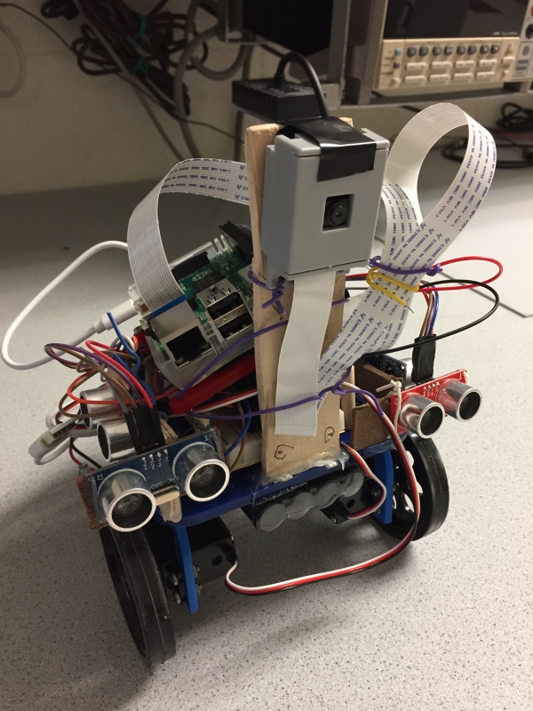
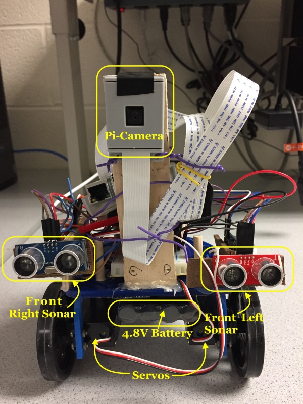
The project utilized chassis and wheels supplied during Lab 3 of the course. As assembly was completed during that session, our task was limited to installing the sensors and Pi-camera. To supply power to the servo motors, we acquired an external 4.8V battery. Additionally, a power bank was employed to energize the Pi.
Design & Testing
Hardware
Servo Motors
We opted for Parallax continuous rotation servo motors (datasheet available here) to propel the robot's wheels. These servo motors offer seamless bidirectional continuous rotation and boast easy installation and operation. Below, in Figure 1, you'll find the wiring diagram for the servos.
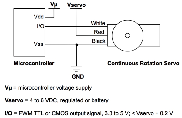


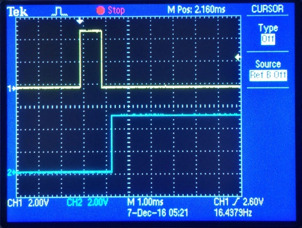
As evident, the motor speed is regulated through a PWM input signal. In our particular application, we opted for 1.4 milliseconds and 1.6 milliseconds as the ON times for clockwise and counterclockwise rotations, respectively. This configuration ensures the motors operate below maximum speed, which suited our needs perfectly as high speed wasn't a priority. Figure 3 below illustrates the PWM signal captured on the oscilloscope for the stopped state (1.5 milliseconds ON time).

Ultrasonic Sensors
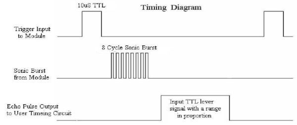
Find Bot incorporates four ultrasonic range finding sensors to perceive its surroundings. Two sit front and center, with one each adorning the left and right peripheral. These HC-SR04 modules, sourced from Robot Shop, unleash high-frequency sound pulses and measure their echoes to gauge proximity. Each contains an emitter and receiver circuit along with control logic. When triggered, the sensor emits an ultrasonic chirp lasting 10 microseconds at 40kHz. Any reflections from obstacles in the beam path return to the receiver. By timing the echo pulse duration, the sensor accurately determines distance. As shown in the waveform diagram of Figure 4, farther objects yield longer echo pulses, near ones faster responses. Ranging from 2-400cm with 3mm resolution, the sensors scan Find Bot's vicinity, building a real-time sonic map. Like biological echolocation, they allow the robot to perceive the landscape through active acoustic sensing. Accessing this live spatial data, the Raspberry Pi navigational software skillfully pilots Find Bot among furnishings, continuously monitoring surroundings and adjusting movement to avoid collisions.
Calculating Distances with Sonars
To determine the distance of an object or obstacle from the sensor, we utilize the duration the echo signal remains in the HIGH state. With the speed of sound being 340 m/s, the distance can be calculated as follows: \( d = t_H \times v_{sound} / 2 = t_H \times (340 \, \text{m/s}) / 2 \). The manufacturer recommends a minimum of 60 milliseconds between triggering events to avoid signal interference. Below in Figure 5 are waveforms illustrating trigger and echo signals, depicting an object situated at a considerable distance (left image) and 10 cm away (right image) from the sensor.
Echo Pulse Detection
As previously explained and illustrated in Figure 5 above, once the trigger pulse is initiated and the internal 8-cycle burst is dispatched, the echo pulse rises to a HIGH state. Subsequently, the pulse resets upon the rebound of the signal from the obstacle, reaching the receiving end of the sonar. Accurately measuring the duration of these echo pulses for each sonar is crucial for computing the distance of the object from the sonar. This entails detecting the instance when the echo pulse transitions from LOW to HIGH and waiting until it returns to LOW. By calculating the duration during which the pulse remains HIGH, we can determine the distance of the obstacle from the sonar.
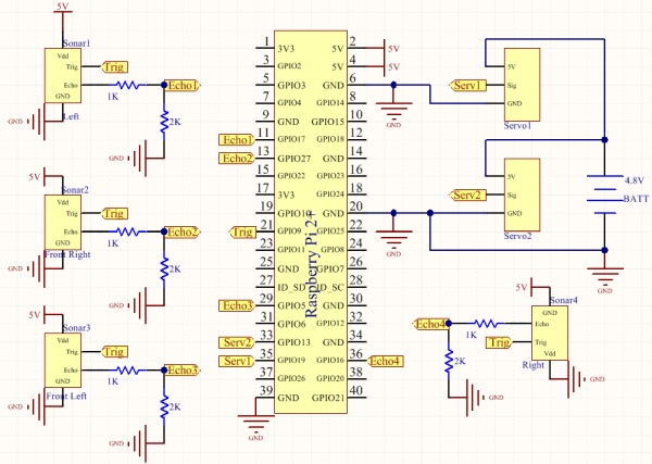
It's noteworthy that a single trigger was activated for all sensors using GPIO pin 21, defined as an output pin. GPIOs 27, 5, 16, and 17 were designated as input pins for the echo pulses of the right front, left front, right, and left sensors, respectively. Figure 8 below provides the schematic representation of our system.
Trigger Pin of the Sonars
The HC-SR04 sonar modules feature four pins: Vcc, GND, Trigger, and Echo, operating at a voltage of 5V supplied by a battery pack, with a working current of 15 mA. Both trigger and echo signals are 5V pulses. To streamline GPIO pin usage, we opted to utilize a single trigger for all four sensors. Given that the GPIO pins output 5V, there was no need for a level shifter or boost converter to drive the trigger pin. Thus, the GPIO pin on the Pi directly connects to the trigger inputs on the sonar modules, as depicted in Figure 8 below. This approach prompted concerns about potential interference between sensors and the ability of a single pin to supply sufficient current to the sonars. However, through testing, we confirmed that triggering all four sensors simultaneously with the same trigger does not compromise measurement accuracy.
Voltage Dividers for Echo Signals
Four voltage dividers were constructed to attenuate the 5V echo pulses from each sonar to 3.3V, compatible with the Raspberry Pi's defined-input pins. This adaptation was crucial due to the GPIO pins' voltage limitation of 3.3V. Utilizing 1kΩ and 2kΩ resistors, we implemented the voltage dividers, as illustrated in Figure 7 above. Displayed below in Figure 7 is the completed assembly of our system, encompassing the Raspberry Pi, sensors, servos, Pi-Camera, and battery pack, all securely mounted on the chassis.
System Design & Schematic
Figure 8 below presents the comprehensive schematic of our system.
Software
Software Development
Our system's software encompasses two primary functions/algorithms: a. Target Detection using OpenCV, and b. Obstacle Avoidance Algorithm. Below are descriptions of the developed algorithms:
1. Target Finding via OpenCV
The primary function of our robot revolves around the recognition of a user-defined RGB color pattern. We opted for the color green as it was uncommon in our testing environment, thus minimizing the chance of detecting random objects. Employing a Pi-Camera for pattern recognition, we first configured the camera by installing the OpenCV library onto the Raspberry Pi. OpenCV, an open-source computer vision and machine learning library, facilitated this process. Our installation procedure involved:
a. Updating and upgrading the Raspberry Pi and existing packages, including installation of image I/O packages for various image file formats.
b. Downloading the OpenCV source code.
c. Installing and compiling the OpenCV source code (initially version 2, later transitioning to version 3 due to encountered difficulties). Installation steps differed for Python 2.7 and 3.
d. Testing the software.
However, we encountered challenges during the setup. Initially, we installed OpenCV version 2 due to limited space on the SD card. Despite investing about 20 hours in setup and testing, we discovered that OpenCV was malfunctioning, causing a significant reduction in Pi speed and rendering the software inoperable, with frequent segmentation faults. To address this, we upgraded to a larger SD card (16GB) and attempted installation of OpenCV version 3. Although this improved the software's functionality, there was noticeable lag, which, given the non-speed-dependent nature of our application, we deemed acceptable to proceed with subsequent tasks. We suspect that either the Pi version (we're using R-Pi 2+) or the Python version may be contributing to the software's sluggish performance.
The next phase involved familiarizing ourselves with OpenCV to enable object recognition. Following research and testing, we successfully programmed the system to recognize the green color based on its RGB pattern. The robot continuously scans for this pattern and moves toward it upon detection (assuming no obstacles obstruct its path).
It's worth noting that the distance to the target is determined by the radius of the detected green pixels. For our purposes, a radius greater than 3 signifies that the robot has yet to reach the target. Once the radius equals 3, the robot executes a 360-degree rotation, indicating successful target acquisition. Furthermore, to maintain awareness of the target's position, we constantly record its x-coordinate. This enables the robot to realign itself with the target if it deviates. Tracking the y-position was unnecessary since the target remained stationary. However, adapting the system to track a moving target would require modifying this condition.
Figure 9 illustrates the software setup for the PiCamera module, alongside other features and included libraries within the project.
Follow this link for complete project: The Object Finding and Obstacle Avoidance Robot: A Step Towards Intelligent Machines