<The Instructable and the code are ready. Enjoy! Leave a comment with you feedback!>
I’m @RedPhantom (aka LiquidCrystalDisplay / Itay), a 14 years old student from Israel learning in the Max Shein Junior High School for Advanced Science and Mathematics. I’m making this project for everyone to learn from and share!
You may have thought to yourself: hmm… I’m a geek… And my children want me to make a project with them…
He wanted to build a robot. She wanted to dress it up like a little puppy. It’s a good weekends project!
The Raspberry Pi is perfect for every use: today we will explicit the abilities of this micro-computer to make a robot. This robot can:
- Drive around and be controlled via LAN (WiFi) using any computer connected to the same WiFi network as Raspberry Pi is.
- Stream video live using the Raspberry Pi Camera Module
- Send sensors data using Arduino
To see what you need for this nice light project just read the next step (warnings) and after that the Wanted: Components step.
Here is the GitHub repo: GITHUB REPO BY ME
Here is the Project Site: PROJECT SITE BY ME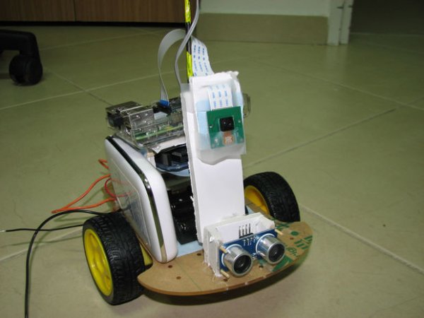
Step 1: Warning: Be Careful Trying This At Home
CAUTION: THE AUTHOR OF THIS TUTORIAL ASSUMES YOU HAVE SUFFICIENT KNOWLEDGE ABOUT ELECTRICITY AND THE BASIC OPERATION OF ELECTRICAL EQUIPMENT. IF YOU ARE NOT CAREFUL AND DO NOT FOLLOW THE INSTRUCTIONS IN THIS TUTORIAL YOU MAY: DAMAGE ELECTRONIC EQUIPMENT, BURN YOURSELF OR CAUSE A FIRE. Please be careful and use common sense. If you do not have the knowledge required for this tutorial (soldering, basics of electronics), please perform with an individual who does. Thank you. And:
THIS INSTRUCTABLE’s AUTHOR REMOVES ANY RESPONSIBILITY FROM HIMSELF FOR DAMAGE CAUSED OR LOST PROPERTY OR PHYSICAL DAMAGE. USE COMMON SENSE.
And:
This is an entry in the Raspberry Pi contest. I will be more than grateful if you vote for me up in the right corner. Thanks! Enjoy.
LICENSING
The program that is available with this Instructable is licensed under GPL v3.
The GPL License gives you:
- the freedom to use the software for any purpose,
- the freedom to change the software to suit your needs,
- the freedom to share the software with your friends and neighbors,
- and the freedom to share the changes you make.
Step 2: Wanted: Components
All you need for this light week-end project is:
- A Raspberry Pi
Any model will do: we will use two USB ports: one for the WiFi adaptor and another for the Arduino.
I’m using Raspberry Pi 2 Model B
- A WiFi Adapter for you Raspberry Pi. Occupies 1 Pi USB port. (Connected to Raspberry Pi)
- A USB-A to USB-B short cable. Occupies 1 Pi USB port. (Connected to Raspberry Pi)
- An Arduino
(Connected to Raspberry Pi)
Again, any model will do. This little micro-controller will receive the output from our sensors and send signals to our DC motors.
I’m using Arduino Uno. - Sensors (Optional). (Connected to Arduino)
These will get information from the environment and collect it for us.
- Dual H-Bridge
An H-Bridge is used to control the motors, like a big transistor. The Arduino sends pulses (PWM, see final step for explanations) to the H-Bridge which powers the DC motors from an external source. (See LOGICAL VOLTAGE and OPERATIONAL VOLTAGE in the final step (Explanations)).
I use an L298N-Based dual H-bridge.
(Connected to Arduino)
- DC Motors
Note: They must be the same model ones so that they’re speed is the same. Using Servo motors is also an option: Hook up the GND (Ground) wire to the arduino and the poer source. The signal to a PWN-able pin on the micro-controller and the PWR wire to an external power source. This method does not require an H-Bridge.
- A Battery Pack for the Pi and Arduino.
I recommend a Battery Bank as it comes with a charging circuit and can be charged from any computer
I use a 5V 5000mAh 1A Battery Bank.
Note: a minimum for 1A is required for the robot to operate normally. Less than that will cause heating and may damage the battery.
(Connected to H-Bridge)
- Breadboard Jumpers
They are very useful little bastards. They connect all of your components together without soldering – the ultimate solution for prototyping.
- 6v Battery Pack / Battery pack for your motors
As I use 4 AA batteries, you should use a battery pack that suits your DC motors. Note: Unlike other components, DC motors (like LEDs) use all of the current given to them and so you should use regular Alkaline batteries and not rechargeable cells. Just be cautious|
(Connected to H-Bridge)
- Platform
As Raspberry Pi is a great platform to create this robot, we need a physical platform to place all of the components on. You can use whatever you want: wood and aluminium are just to great material.
NOTE: If you decide to build your robot with a metal or a conducting material, cover it with a layer of transparent plastic / any other non-conducting material as when you put a board on it, the through-hole pins can short and destroy your board. Not good.
I use a plastic base I bought from E-Bay for 12$. There are many to pick from out there. Even ones that come with motors (like mine). - Knowledge
You mostly need simple programming understanding and basic Linux-environment operating skills. These are simple to acquire– I learned Python and other programming languages via an eBook!
Step 3: Reading Material
Is is recommended that you will go over:
And visit:
- the Raspberry Pi site
- the Arduino site
- the Python site
The GitHub repo and the Site for this project are available on the first page!
Fork us on GitHub!
Step 4: Power Managment
First, we will have to take a look over our component’s power usage. Normally all of them operate on 5V.
Raspberry Pi 2 B (Any model will do) : ~500mA
Camera Module: ~250mA
Arduino (Uno): ~150mA
Ultrasonic Distance Sensor: ~50mA
Sum: 950mA. My battery is capable of delivering up to 1A so it’s all good. If your setup requires more than 10% what the battery is capable of, consider connecting two in parallel or buying a higher-amperage one.
Important note regarding the H-Bridge: If your motors require more than 6V, then connect the power for the H-Bridge to the 12 In DC Pin and not the the 5V input. In that case, the 5V in acts as 5V Output. See your one’s datasheet and/or an instructable.
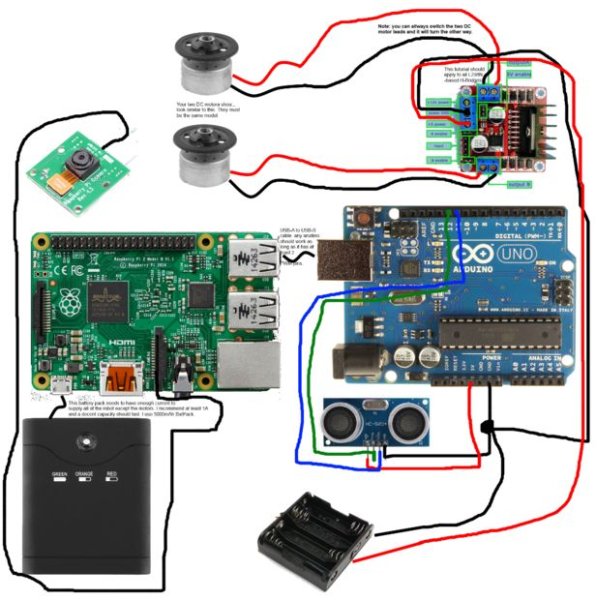
Step 5: Connections
Before we heat up the soldering Iron, we need to go over what should be connected to what. I made this simple chart (MS Paint never lets me down) that describes Where curtain part are located within this robot (btw, my little sister calles it FartBot because of the funny noises the tires make. Mother convinced me to change the name to SmartBot)
The image is built so you can zoom in and see in full resolution and read the small messages I left there.
Step 6: Address for the Pi
The Arduino talks with the Pi according to the plan. And the Pi talks to the computer, so how does this all work?
Lets look at our CIS (Connection Initiation Sequence):
- Raspberry Pi starts
- Arduino Starts
- Raspberry Pi starts TCP Client. It shoots out its IP adress via an LED.
- Raspberry Pi starts Serial Comms service and connects to Arduino
Therefore we’ve established some sort of communication:
Computer <-> Raspberry Pi <-> Arduino
I’ve used Visual Basic .NET (Microsoft Visual Studio 2013 Community) to write the program that talks with the Raspberry Pi and Python to write the Arduino/Raspberry Pi protocol.
All you need to do to know your Pi IP address, is to connect it to an HDMI screen, log in to the Shell and type the command:
hostname -I
Make sure to use a capital “I” (letter “Eye”) for the command to work.
Step 7: The Plan
Now that we’ve got Pi’s IP address we will SSH into it (get access to files, SSH is Secure Shell) and write a file that includes the Server’s IP address. The pi, on startup will do so as well and write the port it’s listening to. Here I will only give a few examples from the code but it is available to download from this step and from the github branch I’ve created. Details later.
It works like so:
- RPi starts up.
- RPi starts the Tcp program on its local IP and a designated port.
- RPI starts to stream video
- RPI shuts down.

Step 8: Going Physical
Now, we are ready to start physically build the whole thing. If you haven’t read step 1 (warning text and licensing) please do so before proceeding. I’m not responsible for any damage caused. And in case of doubt, this robot must not be used for military purposes unless it’s a zombie apocalypse. And even then use common sense.
It is suggested you read the instructables listen in the Reading List.
Download the connection scheme from the “Connections” step.
MOTORS
The motors you’ve bought probably look like this, and it’s OK if they don’t: if they have only two wires (black and red at most cases) it should work. Look up their datasheet online to see their operating voltage and current. Feel free to ask questions in the comment section. I always read them.
H-BRIDGE
I’ve never worked with an H-Bridge before. I googled a bit and found a good instructable explaining the principles of an HB. You can look there too (see Reading List step) and hook yours too. I won’t explain much. You can read there and know all you should about this circuit.
LED
This little lightbolb can run from logical voltage just because it requires almost no current, and a voltage of 3V-5V 4mA-18mA. Optional.
ARDUINO
Arduino will get signals and commands via Serial connection from the Raspberry Pi. We use Arduino to control our motors because Raspberry Pi cannot output analog values via the GPIO.
For more detail: Build your Internet Controlled Video-Streaming Robot with Arduino and Raspberry Pi