
I. Summary
In production life, LED dazzling light control has countless application scenarios, from large to giant outdoor LED display, small to LED indicator of mouse, keyboard and key chain, which can be seen almost everywhere. And Raspberry pi Pico as a new member of the Raspberry Pi open source hardware family, as soon as it appeared, it brought unstoppable heat, at the end of January 2021, the Raspberry Pi Foundation released a heavyweight news, the launch of the Raspberry Pi Raspberry pi Pico into the field of microcontrollers.
This article is to use Raspberry pi Pico and STONE HMI to develop a RGB dazzling light control solution.
II. The functions achieved
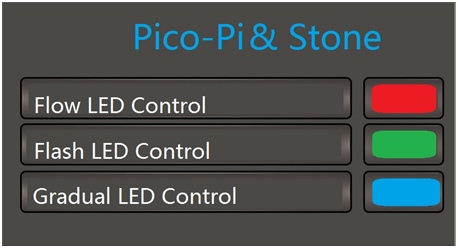
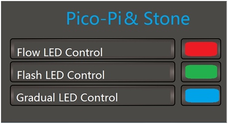
(A) RGB-LED control main interface
The working control selection interface of 3 kinds of RGB LEDs can be jumped to the corresponding interface.
(B) Flowing light control interface
1. red running light.
2. green running light.
3. blue running light.
(C) blinking light control interface
1. 500ms flashing.
2. 1000ms blinking.
3. 1500ms blinking.
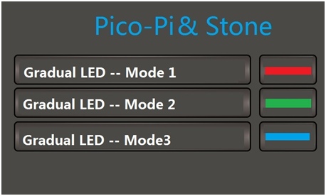
(D) fade light control interface
3 kinds of fading mode.
III. The system principle and composition
(A) System principle
Through the HMI display, the system collects the operator's instructions and sends them to Raspberry pi Pico through the serial port. Raspberry pi Pico analyzes the instructions and controls the light set through the WS2812B compatible timing control signal.
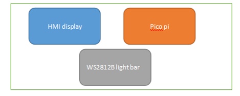
(B) System Composition
The system mainly consists of HMI display, Raspberry pi Pico, WS2812B light bar board, four parts.
IV. System hardware design
(A) HMI display
1. “RGB LED colorful light control” hardware design
Use HMI screen of Beijing STONE Technology co., ltd, model is STVC070WT-01, with integrated TFT display and touch controller.


(1) STVC070WT-01 product features
-Controlled by any MCU.
-Displaying pictures/text/curves.
-65536 color TFT display.
-with/without touch screen.
-RS232/RS485/TTL UART interface and USB port.
-Wide voltage range.
(2) Interfaces
-Power supply interface.
DC power supply from 12V 1A power adapter.
-Communication interface
External communication via RS232 serial port with baud rate of 115200bps.
(B) WS2812b light bar control board
1. Light bar control panel
Using a new member of the Raspberry Pi ecosystem, Raspberry pi Pico.
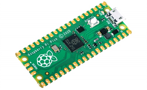
RP2040 Microcontroller
The Raspberry Pi Raspberry pi Pico is designed around the Foundation's new chip, the RP2040 microcontroller. The following are its parameters.
-Dual-core 32-bit ARM Cortex -M0+ processor
-Runs at 48MHz, but can be overclocked to 133MHz
-30 GPIO pins (26 exposed)
-Can support USB host or device mode
-8 Programmable I/O (PIO) state machines
-The RP2040 is capable of supporting up to 16MB of off-chip flash memory, though only 4MB in the Raspberry pi Pico.
-three 12-bit ADC pins.
-UART, SPI, IIC functions.
V. System software design
(A) RGB LED dazzling light control main interface
The development process of HMI
First, create the project and load the required pictures into the project.
Here we make a background picture to display the floor and the upward and downward information through Ico.
Second, use the TOOL-2019 controls to create, dynamically associated relationships; the main controls are: “Animated icon”, “Varialbe icon”;
Third, software simulation and compilation to generate executable files.
Fourth, the HMI screen is connected to the PC via debugging tools and the executable file is downloaded to the screen.
Here, add Button function on the interface, set the effect to the next chapter key triggered image, transfer to the corresponding setting interface.
(B) RGB LED running light control
STONE HMI uses controls such as “Varialbe icon”, “Button Key value return” and audio properties of the controls in order to realize the function of running light control.
(1) STONE HMI software design
First of all, we make the base map, and make the corresponding action effect map for the button trigger, as shown in the following figure.
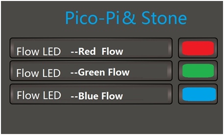
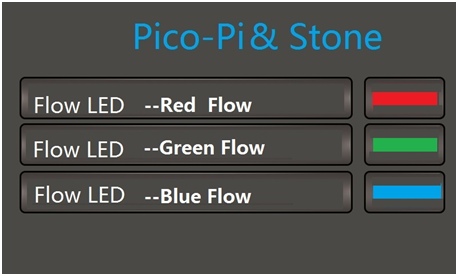
Place the “Button Key value return” control at the corresponding location and set its Button effect property to Figure 11, so that when the touch action occurs, the interface at the location covered by the control will display the content of Figure 11 to achieve the effect of a key press.
-Red Flow is selected command: A5 5A 06 83 00 86 01 00 00.
-Green Flow selected command: A5 5A 06 83 00 87 01 00 00.
-Blue Flow selected command: A5 5A 06 83 00 88 01 00 00.
(2) Raspberry pi Pico console software design
Receive commands from the HMI display through the serial port, parse and call the WS2812b function to drive the LEDs to perform the corresponding actions.
# The state control of the strip, mode=1-3 is the 3-color running light
# mode=4-6 is the interval flashing, 500ms 1s 1.5s
# mode=7-9 is a 3-color color fade
if mode==0x01 or mode==0x02 or mode==0x03:
if no < 7 :
no = no + 1
else: no = 0
time.sleep_ms(500)
if mode == 0x01:
np.fill(0,0,0)
np.set_pixel(no,5,0,0)
np.show()
time.sleep_ms(200)
elif mode == 0x02:
np.fill(0,0,0)
np.set_pixel(no,0,5,0)
np.show()
time.sleep_ms(200)
elif mode == 0x03:
np.fill(0,0,0)
np.set_pixel(no,0,0,5)
np.show()
time.sleep_ms(200)
(C) RGB LED blinking light control
STONE HMI uses controls such as “Varialbe icon”, “Button Key value return” and audio properties of the controls to realize the function of running light control.
(1) HMI software design
First of all, we make the base map, and make the corresponding action effect map for the button press, as shown in the following figure.
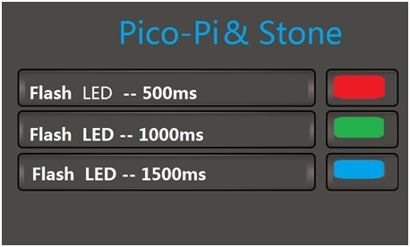
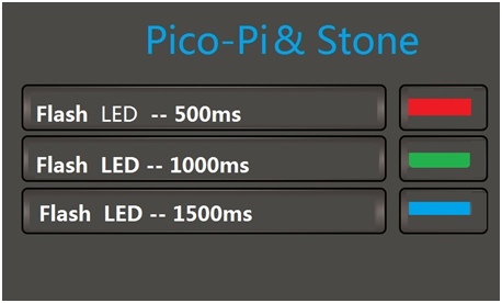
-500ms blinking selected command: A5 5A 06 83 00 89 01 00 00.
-1000ms blinking selected command: A5 5A 06 83 00 8A 01 00 00.
-1500ms blinking selected command: A5 5A 06 83 00 8B 01 00 00.
(2) Raspberry pi Pico console software design
Receive commands from the HMI display through the serial port, parse and call the WS2812b function to drive the LEDs to perform the corresponding actions.
# The state control of the strip, mode=4-6 is the interval flashing, 500ms 1s 1.5s
# The state control of the strip, mode=4-6 is intermittent flashing, 500ms 1s 1.5s
elif mode == 0x04:
np.fill(5,0,0)
np.show()
time.sleep_ms(500)
np.fill(0,0,0)
np.show()
time.sleep_ms(500)
elif mode == 0x05:
np.fill(0,5,0)
np.show()
time.sleep_ms(1000)
np.fill(0,0,0)
np.show()
time.sleep_ms(1000)
elif mode == 0x06:
np.fill(0,0,5)
np.show()
time.sleep_ms(1500)
np.fill(0,0,0)
np.show()
time.sleep_ms(1500)
(D) RGB LED fading light control
HMI-Stone uses controls such as “Varialbe icon”, “Button Key value return” and the audio properties of the controls in order to realize the function of running light control.
(1) HMI software design
First of all, we make the base map, and make the corresponding action effect map for the button press, as shown in the following figure.
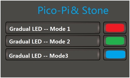
-The 1st fade is selected command: A5 5A 06 83 00 8C 01 00 00.
-2nd fade selected command: A5 5A 06 83 00 8D 01 00 00.
– 3rd fade selected command: A5 5A 06 83 00 8E 01 00 00.
(2) Raspberry pi Pico console software design
Receive commands from the HMI display through the serial port, parse and call the WS2812b function to drive the LEDs to perform the corresponding actions.
# The state control of the strip, mode=7-9 is a 3-color color gradient
elif mode == 0x07:
np.set_pixel_line_gradient(0,7,1,1,1,30,10,5)
np.show()
elif mode == 0x08:
np.set_pixel_line_gradient(0,7,1,1,1,5,10,30)
np.show()
elif mode == 0x09:
np.set_pixel_line_gradient(0,7,1,1,1,10,30,5)
np.show()
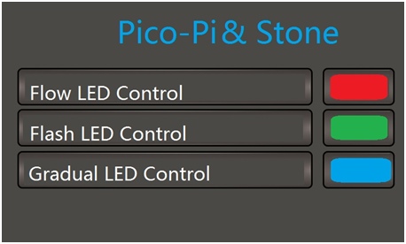
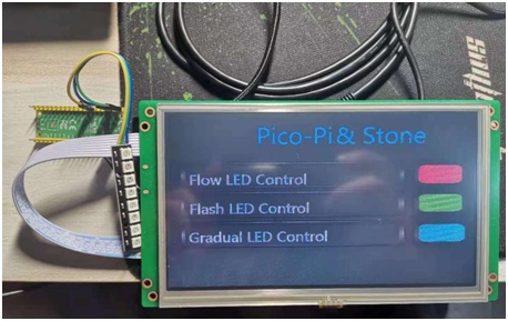
VI. System operation effect test
The effect of the physical demonstration is shown in the following figure.
VII. Future Outlook
This case is to use the screen and Raspberry pi Pico to build RGB dazzling light control unit, which can be extended to control 256 lights with 8 pins each to form a 32*64 3-color dot matrix screen.