
We have utilized Raspberry Pi extensively over an extended period to embark on numerous thrilling projects. However, we frequently encounter a predicament when it comes to selecting the optimal power source for our endeavors. On occasions, the sudden loss of power results in an abrupt shutdown of our Raspberry Pi, potentially leading to OS corruption or, in the worst-case scenario, irreparable damage to the board itself. Therefore, our objective today is to construct a custom Raspberry Pi Zero HAT that can be conveniently attached atop a Pi Zero board or any other Pi Board. This Raspberry UPS HAT will incorporate a TP4056-based charger designed for a single 18650 battery, a holder for the 18650 cell, and an MT3608-based booster. The MT3608 will elevate the input voltage to 5V, enabling it to effectively power the Pi.
We have condensed the entire HAT into a compact and portable PCB board, which was manufactured by 7pcb.com, also known as Bittele. The small size of the board allows us to conveniently transport it alongside our Raspberry Pi. 7PCB is a comprehensive turn-key PCB solution provider with production facilities in both China and Canada. They specialize in PCB fabrication, parts procurement, and PCB assembly, catering to low and mid volumes. We will delve further into these details later on.
In addition to serving as a power source for the Pi, our Raspberry HAT offers supplementary power outlets such as a USB output port, along with several 5V and 3.3V pins. These additional ports and pins can be utilized to power other sensors and modules that we may want to incorporate with our Raspberry Pi. Therefore, in this project, we will demonstrate the process of designing your own Battery HAT for Raspberry Pi and guide you through the fabrication steps using 7pcb.com. Without further ado, let's commence our journey.
Giveaway Alert !!
We are offering a total of three Raspberry Pi Power HAT PCBs, complete with all the necessary components and additional surprises, to our audience. To participate in the giveaway, please visit our dedicated Giveaway Page. There, you will find a comprehensive overview of this Raspberry Pi HAT and also receive information about the giveaway. For a detailed demonstration, be sure to watch the complete overview video.
Components Required for Making Pi HAT
The components required for this project include the TP4056 Module, USB Female Jack, 18650 Li-Ion Battery Holder, 18650 Li-ion Cell, and various SMD components as indicated in the schematic. Please note that the Bill of Materials (BOM) is attached to this article for your reference. You can download it to view the SMD and THT components needed for the PCB.
Power Consumption of Raspberry Pi
As an engineer, it is crucial to perform calculations and estimations to determine the power consumption of a project. Therefore, it is essential to be aware of the idle power consumption of a Raspberry Pi. Below, I have compiled a list of frequently encountered scenarios in which the Raspberry Pi is commonly used, along with their corresponding power consumption values:
|
Component |
Power Consumption (on 5V) |
|
Raspberry Pi zero 2W HDMI off, LED off |
100 mA (0.6 Watt) |
|
HDMI off, LED off, onboard WiFi on |
120 mA (0.7 W) |
|
Raspberry Pi zero HDMI off, LED off, Wifi on |
120 mA (0.7 Watt) |
|
Raspberry Pi 2 B idle |
220 mA (1.1 Watt) |
|
Ab -n 100 -c 10 (uncached) |
450 mA (approx 2.3 Watt) |
|
400% CPU Load |
400 mA (approx 2.1 Watt) |
|
Raspberry Pi 3 B idle |
260 mA (1.4 Watt) |
|
Ab -n 100 -c 10 (uncached) |
480 mA (2.4 Watt) |
|
400% CPU Load |
730 mA (3.7 Watt) |
|
Raspberry Pi 3 B+ idle |
350 mA (1.9 Watt) |
|
Ab -n 100 -c 10 (uncashed) |
950 mA (5.0 Watt) |
|
400% CPU load |
980 mA (5.0 Watt) |
|
Raspberry Pi 4 B idle |
540 mA (2.7 Watt) |
|
Ab -n 100 -c 10 (uncached) |
1010 mA (5.1 Watt) |
|
400% CPU load |
1280 mA (6.4 Watt) |
Note: We have not included the power taken by Mouse and Keyboard or any other peripherals as they will consume the power accordingly and can be added to the above-stated power.
Raspberry Pi HAT Circuit Diagram
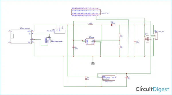
Within the schematic, you will notice the presence of a TP4056 Module, responsible for charging our 18650 cell. It is connected to a slide switch for control. Additionally, a long male header is included to facilitate the mounting of the Raspberry Pi using its GPIOs. Positioned in the center of the schematic, we find the MT3608 IC, which functions as a voltage booster, elevating the power supply from 3.3V to 5V for the Raspberry Pi. The MT3608 serves as a DC-DC boost converter, capable of providing an output of up to 2A. Notably, it supports a wide range of input voltages, spanning from 2V to 24V DC, and can deliver outputs ranging from 5V to 28V. A boost converter is a type of switch-mode power supply that employs a switching device to regulate voltage. In our design, the MT3608 IC serves as the switching module, boasting a high switching frequency of 1.2MHz.
When an inductor (L1) carries a current, it generates a magnetic field. Modulating the current passing through the inductor causes the magnetic field to collapse, leading to the production of a high voltage spike. By utilizing a high switching frequency IC like the MT3608, this phenomenon is harnessed to induce and collapse the magnetic field of the inductor. During the off state of the switching module, the voltage spike travels through the Schottky diode (D1) and is stored in the capacitor (C2). As a result, the voltage across the capacitor increases, yielding a higher output voltage level. The presence of the Schottky diode (D1) is crucial for preventing reverse current from flowing back into the circuit.
To establish the desired output voltage of the booster, it is necessary to calculate the appropriate resistor values. In this case, we aim to achieve approximately 5.2V for powering the Raspberry Pi. Thus, the relationship between the resistor values can be determined as follows:

Where Vref = 0.6
And Vout is 5.2V
So, I have taken up the combination of 1.2K Ohm and 150 Ohm resistors as R1 and R2 respectively that is giving me almost 5.2V.
Circuit and PCB Layout
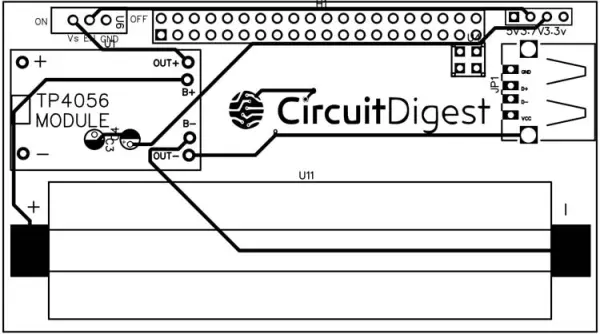
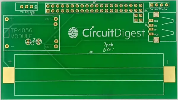
Here is the PCB Layout Image for your reference. Additionally, I have included a 3D view of the PCB that I created. You can download the complete gerber file of the PCB, which allows you to proceed with ordering your PCBs on 7pcb.com. To initiate the ordering process, please follow the steps outlined below.
Ordering PCBs from 7PCB
Obtaining the fabrication of your PCBs from 7PCB (also known as Bittele) is a straightforward process that involves following four simple steps.
Step 1: Launch your preferred web browser and navigate to the website 7PCB.com, which will direct you to their homepage. From there, click on the “Instant Online Quote and Order” option, which will lead you to the corresponding page.
If this is your first time using 7PCB, ensure that you have already registered for an account. As for myself, I already have an account, and it is currently logged in.
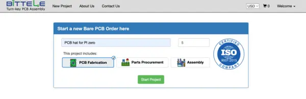
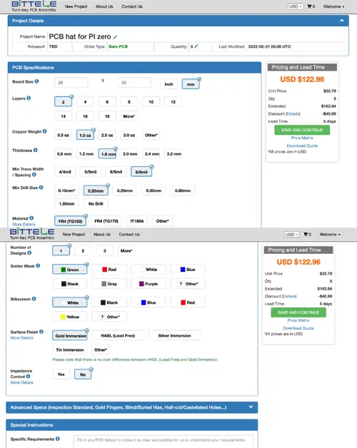
Step 2: Bittele provides comprehensive turn-key solutions, which means they not only handle the fabrication of your PCB boards but also assist in sourcing the appropriate components for your board and even offer assembly services. In my case, I am solely interested in ordering the PCB boards, so I selected only the “PCB Fabrication” option and disabled the other two options. Then, I proceeded to enter a project name and the required quantity of PCBs before clicking on “Start Project.” This action directed me to the following page.
On this page, you have the option to input the size of your PCB and other necessary parameters. In my case, I mostly kept the default values. On the right side, you can view the total cost for fabricating your PCBs. After reviewing the cost, you can click on “Save and Continue” to proceed.
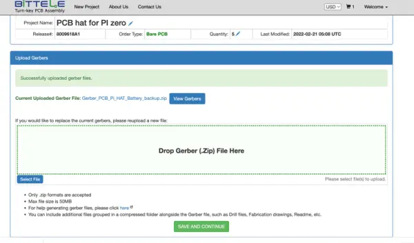
Step 3: Moving on to the next page, you will find the option to upload the Gerber file for your project. In the image provided below, you can see that I have attached the Gerber file for the Raspberry Pi Battery HAT PCB. Once you have uploaded the file, simply click on “Save and Continue” to proceed to the next step.
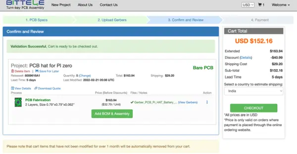
Step 4: The final step involves entering your shipping details and completing the payment process. Begin by selecting the country to which your PCB needs to be shipped. In my case, I have chosen “India.” Once you have confirmed the final price, click on “Checkout” to proceed. Provide your shipping details and proceed to make the payment.
Once these steps are completed, Bittele will commence the fabrication of your PCB boards and ship them directly to your designated address. You can expect the PCBs to be delivered conveniently to your doorstep.
PCB Quality from 7PCB
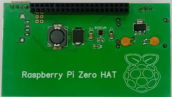
In just a few weeks after placing my PCB order, I received a neatly packaged box containing the PCBs at my specified address. The image provided below showcases both the front and back sides of the PCBs, offering a comprehensive view of their design and layout.
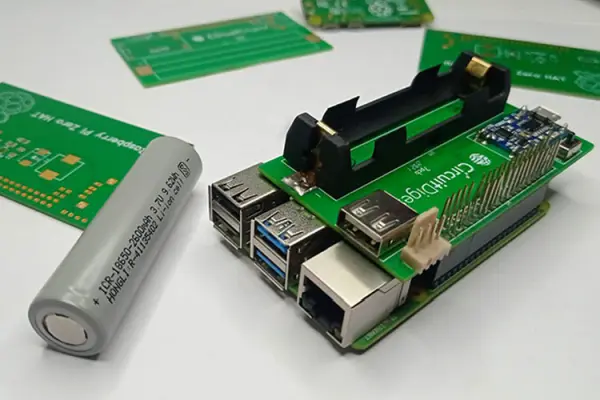
Raspberry Pi Battery HAT – Assembled
The assembled Raspberry Pi Power HAT can be observed in the images below. The battery 18650 is securely inserted into the holder, and all the components are skillfully soldered in place. Additionally, the images illustrate how the board is mounted onto a Raspberry Pi Zero, showcasing the seamless integration between the two.
Testing our Pi Zero Battery HAT
With the completion of our Li-ion Battery Hat for Raspberry Pi, it is now crucial to conduct a thorough testing process. In order to validate the functionality of the setup, we have successfully connected the RPI UPS HAT to a Raspberry Pi. Furthermore, we have utilized the USB port of the HAT to power a 7-inch HDI screen, demonstrating the successful integration and power supply capabilities of the Li-ion Battery Hat.
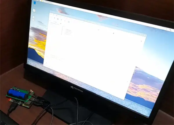
As depicted in the preceding image, the Pi Battery Hat exhibited the capability to not only power and initiate the Raspberry Pi board but also supply power to the LCD screen. The duration for which it can sustain power is contingent upon various factors such as the presence of additional peripherals connected to the Pi and the extent of computational power utilized. For a comprehensive demonstration of its functionality, I encourage you to view the provided video that showcases the complete working of the Pi Battery Hat.
Conclusion
Consequently, we have achieved the successful creation and testing of our customized Pi HAT, compatible with various versions of the Raspberry Pi. This printed circuit board offers great utility when undertaking projects that necessitate a low-powered, independent setup. Moreover, its applications extend beyond this specific use case, making it adaptable for various other projects. We warmly welcome you to share your innovative ideas with us as well. Should you have any inquiries or questions, please don't hesitate to ask in the comment section or forum.
Video