Home automation is growing in popularity because of its ability to provide homeowners with convenience and security. In this project, we will look at how to use an Arduino Nano microcontroller to build a Bluetooth-controlled door lock system and its PCBA manufacturing process. For those who are new to electronics and Arduino programming, this project is ideal. By the time you finish following this tutorial, you will have constructed a door lock system that works perfectly and can be operated wirelessly from your smartphone via Bluetooth.
Components Required:
Arduino Nano
HC-05Bluetoothmodule Relay module
Solenoid door lock Jumper wires Bread board Power supply
Step 1: Understanding the components
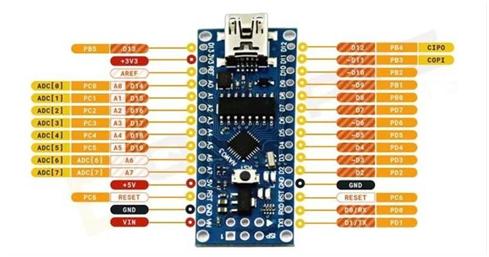
Arduino Nano: A small microcontroller board built on the ATmega328P microprocessor is called the Arduino Nano. It has built-in communication interfaces likeSPI,I2C,andUART and it provides digital and analog pins. The Nano is our project’s brain it will take instructions from the HC-05 module and adjust the door lock mechanism accordingly.
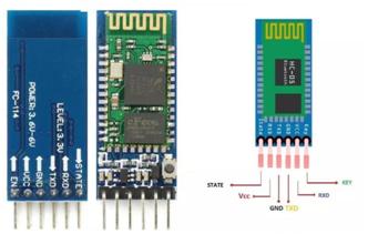
HC05 Bluetooth module: Wireless communication between our Arduino Nano and external devices, such as smart phones or tablets, is made possible via theHC-05Bluetoothmodule. It can couple with our smartphone and accept commands from it when it is in slave mode. The HC-05 allows for easy integration into our project because of its straightforward serial communication interface.
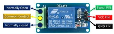
Relay module: it functions as an electromechanical switch controlled by an Arduino digital signal. It will be used to operate the solenoid door lock, turning it on and off in response to commands from the HC- 05module.
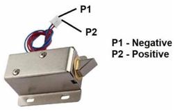
Solenoid door lock: An electrically operated lock that physically locks or unlocks doors is called a solenoid door lock. We can use Bluetooth commands from our smart phone to remotely lock and open the door by connecting it to the relay module.
Step 2: Understanding UART protocol
In electronics, UART (Universal Asynchronous Receiver/Transmitter)is a popular serial communication protocol. By sending bits successively along a communication channel, it makes data interchange
between devices easier. Usually, only two wires are needed one for data transmission(TX)and another for reception (RX).
Asynchronous communication: The asynchronous nature of UART is one of its primary characteristics.UARTfunctionsasynchronouslyincontrasttosynchronouscommunicationprotocols, which rely on an independent clock signal to synchronize data transfer. This indicates that a predetermined baud rate is agreed upon by the transmitter and receiver to synchronize their communication, rather than a continuous clock signal being used to transfer data.
BAUD rate: In a UART communication system, the baud rate controls the speed at which data is transferred between devices. To guarantee effective communication, it indicates the quantity of symbols (bits) sent every second and needs to be the same for both the transmitting and receiving devices. The bits per second(bps)of9600, 19200, and115200areexamplesofcommonbaudrates.
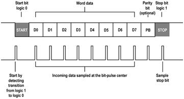
Data format: Data transmission in UART communication usually takes place in a frame format. A start bit, an optional parity bit for error detection, a customizable amount of data bits (usually 8 bits), and one or more stop bits to denote the end of the frame make up each frame. In order to accurately understand the transmitted data, the transmitter and receiver must agree on the frame format and baud rate in the absence of a constant clock signal.
UARTinArduinoandHC-05communication: Understanding UART protocol is crucial for designing and implementing serial communication systems in embedded applications like our Bluetooth- controlled door lock system. In our project, the Arduino Nano and HC-05 module communicate using UART protocol. The Arduino Nano acts as the UART transmitter (TX), sending commands to the HC-05 module, which serves as the UART receiver (RX). Both devices must operate at the same baud rate to ensure successful communication. The Arduino Nano generates the appropriate UART frames to transmit data to the HC-05 module wirelessly.
Step 3: Writing the components
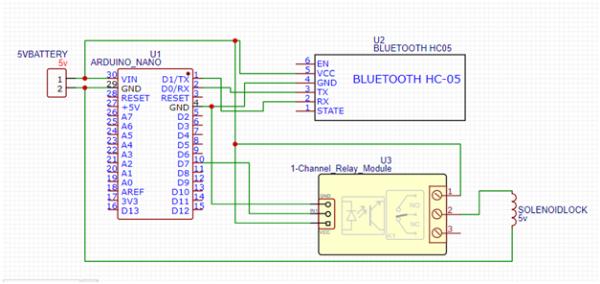
Follow these connections to wire up the components: Connect the TX pin of the HC-05 module to pin 1 (TX) of the Arduino Nano.
ConnecttheRXpinoftheHC-05moduletopin0(RX)of the Arduino Nano.
Connect the VCC and GND pins oftheHC-05moduletothe5VandGND pins of the Arduino Nano respectively.
Connectthecontrolpinoftherelaymoduletopin7 of the Arduino Nano. Below is the schematic.
Step 4: Writing the Arduino Code
We’ll use the Arduino IDE to write the code for our project. The code will initialize the relay pin a san output and setup serial communication with the HC-05 module. It will then read incoming Bluetooth commands and control the operation of the door lock system accordingly.
#defineRELAY_PIN7     //Define the pin connected to the relay
#defineLOCKED_STATELOW//Define the state to activate the relay(LOW or HIGH)
void setup(){
pin Mode(RELAY_PIN, OUTPUT);// Set relay pin as output digital Write(RELAY_PIN,!LOCKED_STATE);//Initialize relay state
Serial. begin(9600);  //Initialize hardware serial for communication with HC- 05
Serial. print ln(“Bluetooth device ready!”); delay(1000);
}
void loop(){
if(Serial. available()){
charcomm and=Serial. read(); if (command == ‘a’) {
digital Write(RELAY_PIN,LOCKED_STATE);//Activate the relay(lock the
door)
Serial. print ln(“Door locked”);
}else if(command==’b’){
digital Write(RELAY_PIN,!LOCKED_STATE);//Deactivate the relay(unlock the
door)
}
}
Serial. print ln(“Door unlocked”);
delay(20);}
Step 5: Testing the system
Turn the system on by providing it power supply after uploading the code to the Arduino Nano. With the help of Bluetooth, pair your smartphone or tablet with the HC-05 module. Install a Bluetooth terminal app on your device and send’ a’ to lock the door or ‘b’ to unlock it. With the help of a relay click sound, you can indicate that the door lock has been activated or deactivated accordingly.
Step 6: PCB Layout for the Bluetooth-controlled door lock system
Now you have completed the schematics and want to design the PCB for your Bluetooth-controlled door lock system. Please transfer your schematics to your PCB design software place components and connect them according to the schematic diagram. You can make a double-sided PCB for the Bluetooth-controlled door lock system for effective using the space and can make it a 2, 6, or 6-layer PCB. While routing the traces to connect the components, take care of keeping proper line width/space, avoiding loops, creating solid ground planes, and designing power distribution traces to ensure adequate power delivery to all components.
After routing the wires, perform a design rule check to identify and modify errors. Then generate the Gerber and drill files and PCB assembly drawings.
Step 7: PCBA Manufacturing for Bluetooth-controlled door lock system
To bring your Bluetooth-controlled door lock system design into real products, you can work with a one-stop PCBA manufacturer PCBONLINE. You can not only ensure the design for manufacturing (DFM) and have the PCB prototypes and PCBA sampling but also take bulky production including the OCBA and final product box builds.
Conclusion: In conclusion, our project, which combined an Arduino Nano with an HC-05 Bluetooth module to create a Bluetooth-controlled door lock system, is an excellent example of how technical creativity and real-world application can come together. We skillfully integrated hardware parts, software algorithms, and communication protocols through system integration to produce a workable and intuitive solution.
The HC-05 module and Arduino Nano can communicate data efficiently thanks to the adoption of the UART communication protocol, underscoring the significance of communication protocol expertise in engineering design. We made sure that our system not only satisfies functional requirements but also improves use and convenience by placing a high priority on safety, dependability, and user experience.
This project emphasizes the value of holistic problem solving, in which user interaction, software, and hardware issues are carefully matched to get the best results. Looking back on our trip, we see how engineering can be a game-changer in solving practical problems and advancing technical innovation.