
Ⅰ Overview of Conventional FPGA Design Tools
Hardware description languages (HDLs) like VHDL and Verilog became the main languages for defining the algorithms that execute on the FPGA chip over the first 20 years of FPGA development. These low-level languages combine some of the advantages of existing textual languages with the understanding that you are designing a circuit on an FPGA. In order to use the resulting hybrid syntax, signals from external I/O ports must be mapped or connected to internal signals, which are then routed to the functions that house the algorithms. These consecutively running processes can make references to other FPGA-based functions. However, a sequential line-by-line flow makes it difficult to understand the job execution on an FPGA's real parallel nature. HDLs reflect some of the attributes of other textual languages, but they differ substantially because they are based on a dataflow model where I/O is connected to a series of function blocks through signals. Nowadays, HDL languages are nowadays the preferred way to create FPGA designs like Zynq-7000 SoC, FPGA Spartan-7, Artix-7 FPGA, Virtex-7 FPGAs, Kintex-7 FPGAs, and so on.
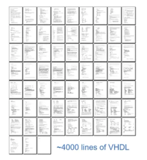
It is common practice to develop test benches in HDL to wrap around and exercise the FPGA design by asserting inputs and checking outputs in order to later validate the logic that an FPGA programmer produced. A simulation environment that replicates the hardware timing behavior of the FPGA chip and shows all of the input and output signals to the designer for test validation is used to run the test bench and the FPGA code. It frequently takes longer to build the HDL test bench and run the simulation than it does to create the original FPGA HDL design.
After using HDL to create an FPGA design and verifying it, you must feed it into a compilation tool that takes the text-based logic and, using a number of intricate steps, converts it into a configuration file or bitstream that specifies how the components should be connected. You frequently need to define a mapping of signal names to the pins on the FPGA chip you're utilizing as part of this multistep manual process.
Ⅱ Programming FPGAs with VHDL
VHDL is a language used at various levels of abstraction to describe digital electrical circuits. VHSIC (Very High Speed Integrated Circuits) Hardware Description Language is the name of the acronym VHDL. This means that the design process can be sped up using VHDL. VHDL is NOT a programming language, and this cannot be stressed enough. Therefore, being able to construct digital circuits using its syntax does not necessarily follow from knowing its syntax. Asynchronous and synchronous circuits can be described using the HDL (Hardware Description Language) called VHDL.
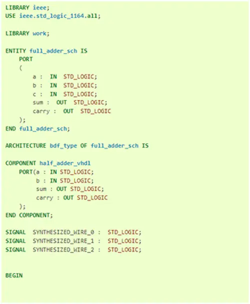
In particular, VHDL enables the specification of a circuit's functionality via directives, much like most common programming languages do. This permits not just the description of a circuit's structure (from simpler subcircuits). The primary goal of an HDL is to imitate a circuit's logical behavior using a description language that is very similar to software description languages.
Utilizing simulation tools that accurately mimic the operation of the circuit in question, digital circuits that are specified in VHDL can be emulated. Developers employ a set of IEEE-standard rules for this purpose, which describe the syntax of the language and how to simulate it. Additionally, there are numerous programs that convert VHDL code into a file that can be downloaded and used to program a reconfigurable device. Synthesis is the term for this process. A particular tool performs the synthesis process in a very specific manner that is significantly different from what other synthesis tools accomplish.
Ⅲ Programming FPGAs with Verilog
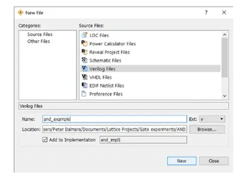
A hardware description language is Verilog. (HDL). This language, along with its rival VHDL, is the most used one for programming FPGAs. Why would you want to learn a difficult programming language when you can program an FPGA using a schematic that you are likely already familiar with and understand? The truth is that, as designs get more complex, it's actually simpler to represent them in a programming language than it is to draw them.
Verilog has features that are similar to those found in programming languages, such as “if” statements, code blocks, and the ability to add and subtract numbers.
Ⅳ Overview of High-Level Synthesis Design Tools
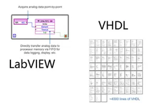
Some of the biggest barriers to the conventional HDL design process have been eliminated by the development of graphical HLS design tools like LabVIEW. Because parallelism and data flow are clearly represented in the LabVIEW programming environment, users with both knowledge and little experience in conventional FPGA design procedures can take use of FPGA technology. Additionally, you may use LabVIEW to include pre-existing VHDL into your LabVIEW FPGA designs so that past intellectual property (IP) is preserved. There is no need to rewrite code in VHDL to match temporal or resource constraints because LabVIEW FPGA is so closely connected with hardware, unlike many HLS code generators.
Then, LabVIEW provides facilities right in the development environment to simulate and validate the behavior of your FPGA logic. You can build test benches to put your design's logic to the test without knowing the low-level HDL language. Additionally, by exporting to cycle-accurate simulators like Xilinx ISim, the versatility of the LabVIEW environment enables more experienced users to model the timing and logic of their designs. The compilation process is automated using LabVIEW FPGA compilation tools, allowing you to start it with the press of a button and receive reports and faults, if any, when compilation stages are finished. If your FPGA design does lead to timing issues, LabVIEW graphically shows these crucial routes to speed up the debugging process.
Ⅳ Programming FPGAs with LabVIEW
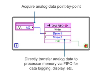
Counters are a great fit for FPGA implementation, and LabVIEW makes it easy to create them graphically. In LabVIEW FPGA, I/O nodes can be used to create analog signals and perform analog measurements. Contrary to CPUs, FPGA hardware enables genuine parallel code execution, and LabVIEW FPGA features graphical loop structures to enable the concurrent execution of various elements of your block diagram. Graphical block diagrams may execute in hardware on the order of microseconds and nanoseconds thanks to LabVIEW FPGA.
Discover the single-cycle Timed Loop, a unique LabVIEW FPGA structure that enables size and speed optimization of any FPGA design. When changing states, mechanical switches and relays frequently bounce. LabVIEW FPGA can be used to construct debounce circuitry to filter out undesirable digital edges. To transmit data across several loop iterations, LabVIEW FPGA now offers Feedback Nodes in addition to shift registers. Case structures are useful for developing unique hardware triggers and state machines since they may be used to selectively activate different elements of your FPGA design.
With LabVIEW FPGA, you may implement various timing engines in hardware and achieve truly independent operation. Most data collecting devices are designed to share sample clocks and triggers.
Ⅵ Conclusion
FPGA technology is being used more frequently as a result of advanced tools like LabVIEW making FPGAs more available. However, it is still crucial to examine the FPGA's internal workings and understand the extent to which block diagrams are translated into silicon for execution. The easiest strategy to find the best FPGA chip for your application is to compare and choose hardware targets based on flip-flops, LUTs, multipliers, and block RAM. When developing, it's quite helpful to understand resource usage, especially when maximizing for size and performance.