
1.Background
In modern times, there is a growing emphasis on home security. Home security encompasses the combination of security hardware installed on a property and the implementation of personal security practices. The hardware aspect involves doors, locks, alarm systems, lighting, motion detectors, security camera systems, and other protective measures.
However, existing home security devices often require the transmission of personal data to the cloud, exposing users to potential privacy risks. Additionally, reliance on cloud servers for data processing makes it inconvenient for users to modify control conditions.
In this project, the team utilizes Raspberry Pi as a server to replace the cloud server, effectively addressing the data privacy concern. Raspberry Pi is a compact single-board computer, known for its impressive processing capabilities. By connecting sensors to the Pi and programming it accordingly, users can manage the data collected. Whenever Raspberry Pi detects unusual occurrences, such as excessively low temperature or the presence of unfamiliar movement, it can immediately send email alerts to the users.
The cost-effectiveness of Raspberry Pi is also noteworthy, as it is priced at $35 for a Raspberry Pi 3 and only $5 for a Raspberry Pi 0. This affordability prompted the team to initially design with Raspberry Pi 3 and later transition to Raspberry Pi 0 for the project.
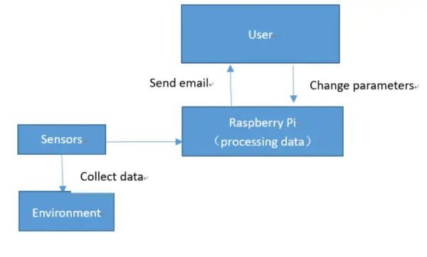
The home security system design involves connecting all the sensors, such as the PIR sensor, temperature, and humidity sensor, directly to Raspberry Pi. Raspberry Pi functions as the server, handling all the data gathered by these sensors. When Raspberry Pi detects any suspicious activity or anomaly, it can promptly send a warning email directly to the user, eliminating the need for external cloud-based data sharing and control.
2.Conceptualization
2.1 Designing the Software
Our project relies on Raspberry Pi as the foundation, with all sensors directly connected to it. Raspberry Pi acts as the server, processing all the data collected by these sensors. In the event of any anomalies detected by the Pi, it can promptly send a warning email to the user. The overall system design of our solution is depicted in the diagram below.
2.1.1 Sensor Configuration
In our project, we have two sensors to manage: the PIR sensor and the temperature and humidity detection sensor. To handle these sensors programmatically, we adopt the concept of object-oriented programming, treating each sensor as an individual object. During the object's construction, we allocate a PIN number and initialize the corresponding input/output state.
Furthermore, each sensor possesses a method to execute its functionality, enabling it to detect and collect environment parameters. The programming aspect is relatively straightforward as we have access to comprehensive documentation for these sensors, making the implementation process smooth. For instance, when dealing with the PIR class, we can employ the following code to initialize it:
p = pir.pir(PIN_NUM)
In our program, we created a PIR sensor object, and the code structure for the DHT11 sensor is quite similar. To operate these sensors, we simply call the detecting function, which doesn't require any parameters and can return the desired data. This detecting function plays a crucial role in the class.
For the PIR sensor, we read the voltage from the GPIO, while the DHT11 utilizes a 1-wire communication protocol, enabling data reading from a single GPIO pin. In this protocol, a low level of 50us followed by a high level of 26-28us represents 0, while a low level of 50us followed by a high level of 70us represents 1, providing the basic timing sequence. The bus remains in a high idle state until the host pulls it down, awaiting a response from the DHT11. To ensure that DHT11 detects the host's start signal, the host holds the bus down for more than 18 milliseconds. After DHT11 receives the host's start signal, it waits for the end of the signal and then sends an 80us low-level response signal. When the host sends the start signal, it reads the response signal of the DHT11 after waiting for 20-40us. To implement this aspect, we referred to the official documentation of DHT11 [8] instead of using the standard library. This approach allowed us to avoid reading invalid data and offered more flexibility in our implementation.
In the upcoming Issue section, we will introduce this part in more detail. For the PIR sensor, the detecting function returns a Boolean value, while for the DHT11, it returns an array with two float numbers: the first representing the temperature and the second indicating the humidity.
To ensure continuous sensor operation, we call the detecting function in a loop. As demonstrated in the following code example for the PIR sensor:
p.detect()
With just three lines of code, we can effectively operate the sensor, offering significant flexibility for unit testing and ensuring the overall program remains maintainable.
2.1.2 Sending Emails
Implementing the email sending functionality using Python's standard library is fairly straightforward, but it requires a substantial amount of code. To improve the program's clarity, we've decided to treat it as an object. Within the constructor, the customer's email address will be initialized. Below are the example code snippets.
se = sendemail.sendEmail(the customer’s email address)
Next, our program includes an email sending class. To send an email, we can use the “mail” method, which takes seven parameters: the current PIR state, the current temperature and humidity, the customer's specified maximum and minimum temperature limits, and the maximum and minimum humidity thresholds.
Inside the main loop, we retrieve the current values from the sensors and obtain the limitations from the configuration file. The “mail” function is then called, returning a Boolean value to indicate whether the email was sent successfully. With all these parameters in hand, we proceed to send the email, Below is the example code:
ret = se.mail(temp,min_temp, max_temp, humid, min_hum, max_hum, pir_detect)
The code allows us to effortlessly send an email to the customer, who typically receives it within approximately 20 seconds. If desired, we can print the value of “ret” to test the current network condition.
2.1.3 Main Program Execution
The main program consists of two primary parts: the initialization phase and the main loop. During initialization, necessary components are set up. The main loop continuously collects data from the environment, analyzes it, and determines whether an alerting email needs to be sent.
During the initialization phase, various models, such as those for sensors and email sending, are created using their respective constructors. Additionally, certain flag values are set, and parameters are retrieved from the configuration file.
The main loop operates as an infinite loop, where we continuously invoke the sensor object's detection function to collect data. Based on this data, we update the corresponding flag values and determine whether to send the email alerts. Following each alerting email, the system resets all flag values and enters a sleep mode for approximately 5 minutes to prevent the sending of redundant emails.
2.2 Hardware Implementation
In our project, we will directly connect all the sensors to the Raspberry Pi, which will serve as the central server to process the collected data. The Raspberry Pi is capable of detecting any anomalies and can promptly send warning emails to users when necessary. Therefore, the core aspect of our hardware design is selecting appropriate sensors and establishing direct connections with the Raspberry Pi.
The primary objective of our project is to identify and report any unusual temperature, humidity, and motion patterns within a house. To accomplish this, we employ a PIR motion sensor, a temperature sensor, and a humidity sensor, all of which are connected to the Raspberry Pi using GPIO connections.
2.2.1 PIR Sensor
PIR sensors, known as “Passive Infrared” sensors, have the capability to detect motion. Infrared radiation is emitted by all objects to some extent, with higher temperatures resulting in greater radiation emission. PIR sensors operate by identifying changes in the infrared radiation emitted by warm objects, allowing them to sense motion effectively.
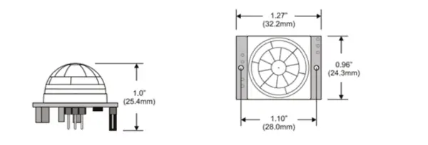
For this project, we have opted to use the HC-SR501 PIR motion sensor due to its cost-effectiveness and user-friendly nature. The internal components of the HC-SR501 PIR motion sensor are depicted below:
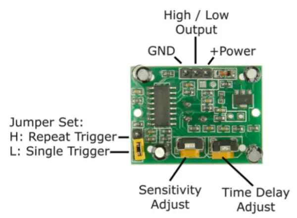
The HC-SR501 PIR motion sensor is equipped with three pins: GND, +power, and high/low output. During idle periods when no motion is detected, the digital output remains low. However, when motion is detected, the digital output pulses high (at 3.3V), and we utilize our Raspberry Pi to detect this change. We employ the sensor to detect human motion.
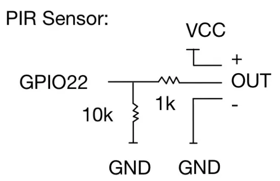
Below is the pin map of the HC-SR501 PIR motion sensor:
2.2.2 Temperature and Humidity Sensor
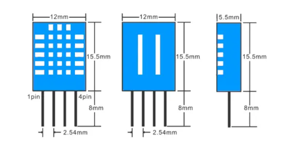
For our project, we have selected the DHT11 temperature and humidity sensor to gather temperature and humidity information from the house. The DHT11 sensor is a compact module that offers digital readings for both temperature and humidity.
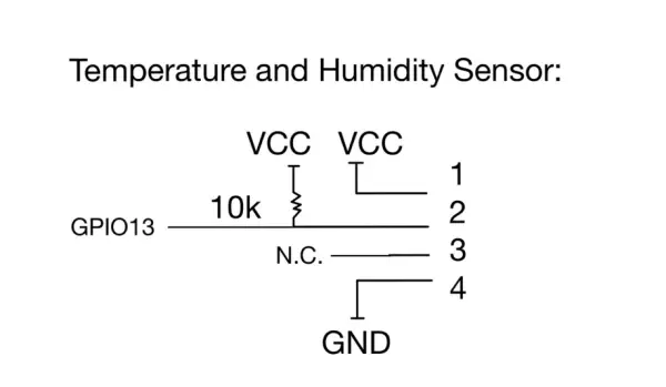
The DHT11 temperature and humidity sensor utilizes a humidity sensor and a thermistor to measure the ambient air conditions, and it transmits a digital signal through the designated data pin. We opt for the DHT11 sensor due to its ability to operate with just one wire for the data signal. Below is the pin map of the DHT11 temperature and humidity sensor.
2.2.3 Connect Sensors to Raspberry Pi
Once we have selected the appropriate sensors, the next step involves directly connecting them to the Raspberry Pi. Initially, we utilized Raspberry Pi 3 for the design. The GPIO pinout for Raspberry Pi 3 is displayed below:
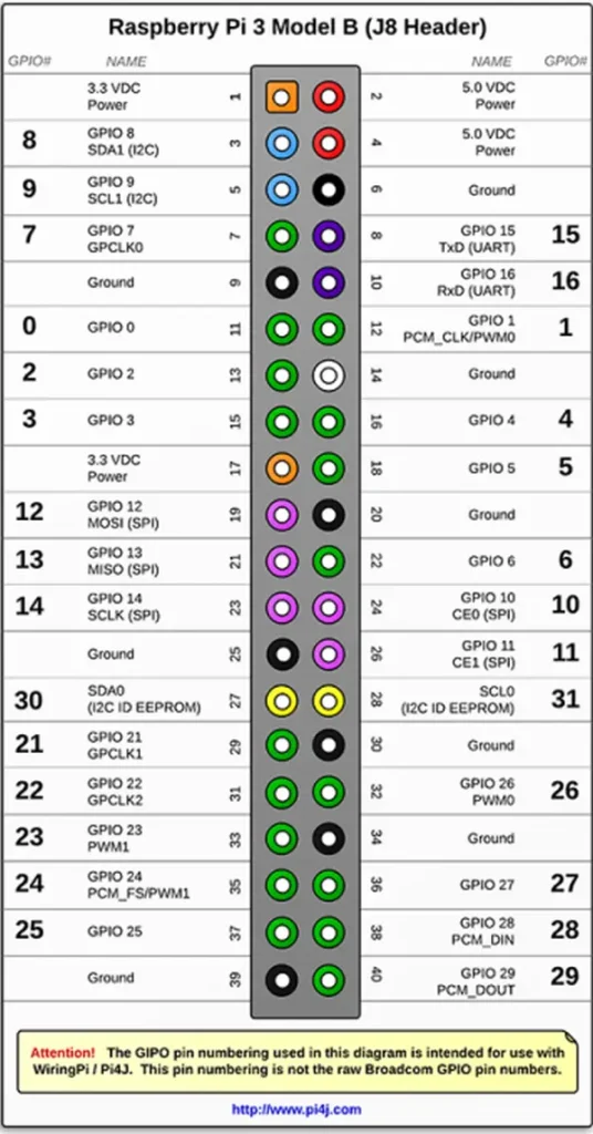
We establish a connection between the PIR motion detector and GPIO19 in the Raspberry Pi. The PIR's output remains low (0V) under normal conditions, but when motion is detected, it switches to high (3.3V). Consequently, we configure our GPIO pin for the PIR-OUT as an input, and then utilize Python to detect any voltage fluctuations.
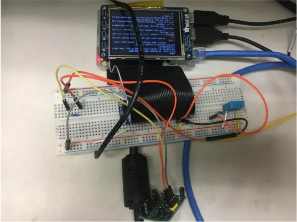
The DHT11 temperature and humidity sensor necessitates only three connections to the Pi: 3.3V, ground, and one GPIO pin. For this project, we connect the humidity and temperature sensor to GPIO13. We utilize a breadboard for the design and testing, as depicted below:
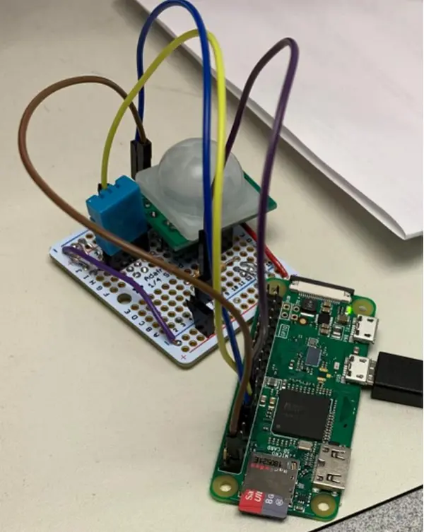
Upon completing the design phase, we made a transition from Raspberry Pi 3 to Raspberry Pi 0. Consequently, we need to directly connect the two sensors to Raspberry Pi 0. The GPIO pinout for Raspberry Pi 0 is displayed below:

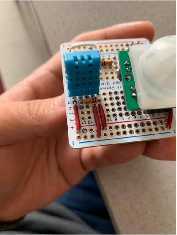
Additionally, to facilitate packaging, we replaced the breadboard with a more compact board. For this purpose, we selected the Perma-Proto Quarter-sized Breadboard. Rather than soldering the components onto the board, we opted to use jumper wires directly. The designed board, featuring the two sensors, is presented below:
2.3 Mechanical Design
The mechanical aspect of the project holds equal importance to other components. While the software and hardware parts may be relatively straightforward, the mechanical part demands meticulous planning. Potential challenges arise, such as selecting the appropriate components, determining the ideal size for a home security system, setting limits for both the components and group members, and dealing with the need for constant design changes during the packaging process (e.g., adjusting pin placements or sensor soldering due to box size requirements). Additionally, careful consideration is required for component placement and sensor positioning. All these factors emphasize the strategic nature of the mechanical part, necessitating close coordination and cooperation among group members.
Here is our construction process: Once we finalized the sensors we needed, the next step was to determine the board and enclosure for our system. Initially, we started with a breadboard, which provided ease of use and versatility, and this was our first prototype. During this phase, we utilized a Raspberry Pi 3.
However, for the second prototype, we switched to the Raspberry Pi 0 W. The reason behind this change was that the Raspberry Pi 3 was more powerful and had additional features such as more USB ports and Ethernet, which were unnecessary for our specific requirements. Furthermore, its larger size was not ideal for our project. Thus, we opted for the Raspberry Pi 0.
For the Raspberry Pi 0, we no longer needed the larger breadboard. Instead, we chose the Perma-Proto Quarter-sized Breadboard, which was much more compact. During this stage, we used jumper wires without soldering them onto the board, which facilitated easier wiring adjustments. To achieve this, we used the Raspberry Pi 0 H version, which came with pre-installed headers, allowing direct attachment of the jumper wires.
Overall, this approach enabled us to streamline our design and construction process, as depicted in Figure 9 below:
After successfully testing the system with jumper wires, we progressed to using core breadboard wires. We found that the breadboard with core wires was perfectly suitable for the device to function, and it also made the potential mass production process much more straightforward. Given this, we made the decision to abandon the idea of using PCB (Printed Circuit Board) design for the project.
To complete the packaging, a power supply for the components and a suitable box for the entire device are required. For the box, we consider using ABS plastic due to its lightweight nature, ease of handling (for drilling holes, etc.), reasonable cost, and extensive variety of options available. The chosen box should be of appropriate size – not too large for a home security device, yet spacious enough to accommodate all the components. As for the power supply, it must efficiently deliver the required power to the components.We opted for a power supply with a 5V 2A output, which meets the necessary specifications for the Pi 0. Below are the components we selected, along with their corresponding mechanical properties:
The PIR Motion sensor (SR501) measures 32mm * 24mm * 25mm in size. As shown in Figure 3.3.2, the PIR sensor comprises two parts: the lower part with non-removable pin feet, which occupy some space during placement, and the upper part, shaped like a hemisphere, requiring installation outside through a round hole.
The Humidity & Temperature Sensor DHT11 has dimensions of 15.1mm * 25mm * 7.7mm. As depicted in Figure 12, the blue part of the DHT11 sensor needs to be positioned outside the box, while its four pins should be securely placed inside the box without direct exposure.
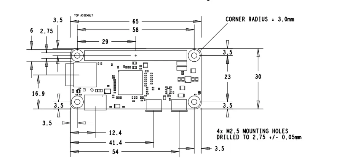
The Raspberry Pi 0 measures 65mm * 30mm in size, as illustrated in Figure 12.
The Quarter-sized Breadboard has dimensions of 44mm * 55mm.
The box measures 111.25mm * 82.55mm * 35.56mm in size.
Once the components were selected, we proceeded with packaging them in the box. It is important to note that the sensors should be placed outside the box. The PIR motion sensor requires direct access to sense motions through its lenses, while the temperature sensor needs to avoid the heat generated by the components inside the box. Consequently, we utilized long wires to keep the sensors separate from the board, rather than attaching them directly to the board.
To ensure proper functionality, the two sensors should be placed at a sufficient distance from each other, preventing their wires from interfering with one another. Additionally, to avoid potential damage, the humidity and temperature sensor is positioned either at the top or bottom of the device, preventing it from protruding and becoming vulnerable to damage.
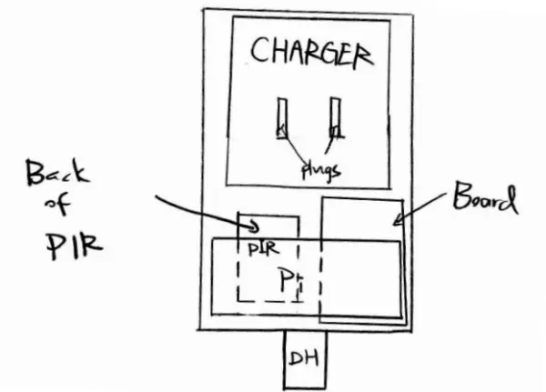
Regarding the power supply, the plugs are located at the back of the box to allow for secure attachment to the wall. As the charger takes up a significant portion of the box's size, it is positioned on the opposite side of the Raspberry Pi, board, and sensors. Thus, in Figure 13, you can observe our original placement design.
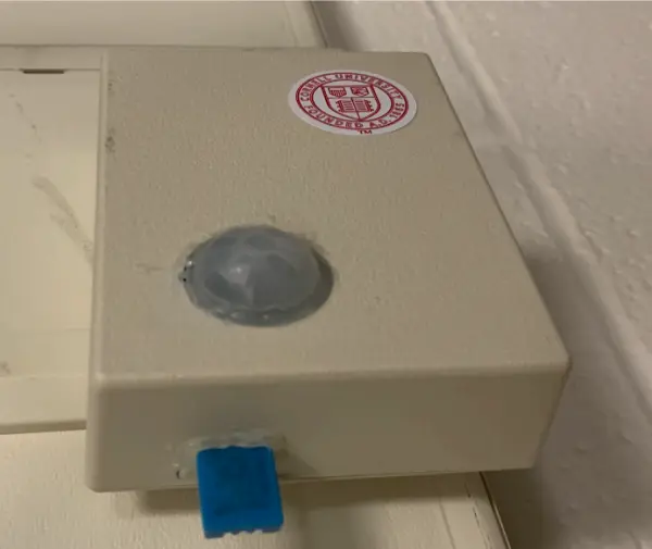
Following the decision to create openings for the sensors and charger plugs, we proceeded with the process. To accommodate the PIR motion sensor, we needed a relatively large hole for its lens. The most effective approach was to utilize a mechanical punch, which enabled us to drill a hole with a diameter of approximately 1 inch, matching the size of the PIR sensor's lens. Figure 14 illustrates the hole we successfully created using the mechanical punch.
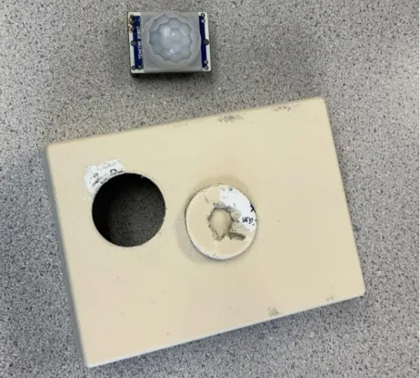
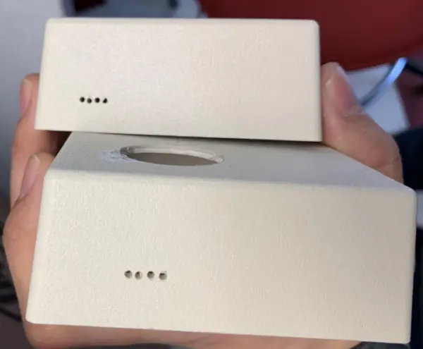
To position the humidity and temperature sensor at the bottom of the box, we ensured that the sensor was placed outside the box, and its pin foot was securely attached to the box and wired to the Proto board. For creating the four small holes needed for the Humidity & Temperature Sensor, we utilized 1mm drill bits. To prevent the drill bits from drifting during drilling, we used a knife, rasp, or screwdriver to create pre-drilled holes. The final appearance of the holes is illustrated in Figure 15.
Next, we proceeded to wire them up to the Proto Board. For these pins, we wanted to avoid exposing them directly, so we used core wire to wrap them up. Here's the method we employed: Firstly, we cut a section of a heat shrink tube slightly shorter than the pin foot's length and slid it onto the foot. Then, we soldered the core wire to the pin foot and slid the heat shrink tube to cover the connection. Using a heat gun, we applied heat to shrink the tube, effectively wrapping and securing the connection. We repeated this process for all the other pin feet.
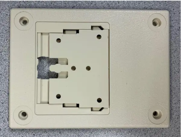
Moving on, we proceeded with the power supply plugs. To ensure a secure connection, the power supply needed to be attached to the back of the box from the inside, allowing the plugs to protrude sufficiently for easy access. We carefully measured the position and size of the power supply plugs, marked them on the back of the box, and then used a rasp to cut holes for the plugs, as depicted below.
To securely attach the power supply, we employed hot glue, which proved effective in keeping the plugs in place and preventing any loose positioning that might affect the device's reliability. Additionally, a removable window was added to cover the back, allowing for further customizations whenever needed. Figure 18 showcases the hole we cut for the plugs.
Once the sensors were in place, we proceeded to position the Pi 0, Proto board, and power supply. As mentioned earlier, the power supply, along with its cable, consumed almost half of the available space within the box. The cable of the power supply was quite sturdy, making it challenging to alter its position easily.
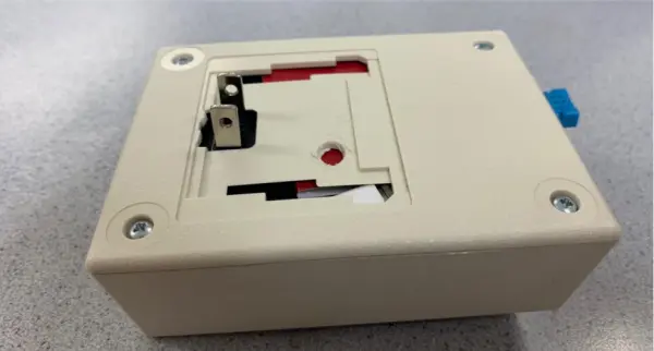
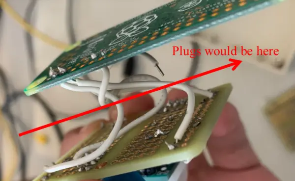
In our initial attempt, we positioned the board and the Pi 0 on opposite sides of the port, as displayed in Figure 18, for our first version of the packaged prototype. However, this arrangement unexpectedly led to an issue. It caused a significant distance between the board and the Pi 0, making it challenging for the wires from both sensors to reach the board. Additionally, the wires between the board and the Pi 0 were prone to snapping. Consequently, we had no choice but to abandon this plan.
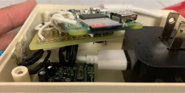
For the second attempt, as depicted in Figure 19, we relocated both the board and the Pi 0 to the same side, close to the plugs area. This adjustment allowed ample space for the wiring of the two sensors and minimized the potential heat impact on the temperature sensor. Additionally, to prevent any short-circuiting issues, we used paper as an insulator to create separation between the wires and the components.
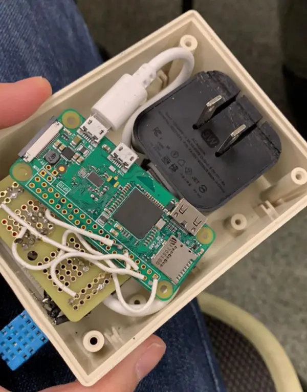
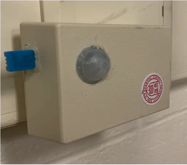
In the end, we successfully placed all the components into the box, creating a fully packaged device. As previously mentioned, this stage demanded constant communication among all team members, and we had to frequently modify both the design and the work we had done. For instance, when we switched the placement plan to have the board and the Pi 0 on the same side as the charger, all the wires had to be resoldered in the hardware part, and the pin numbers might have needed adjustments in the software part. We had to redesign and redo all the wires and pins at each step of the process. Below is the final product we accomplished.
3. Issues
3.1 Software Part Issues
Problem: Occasionally, the temperature and humidity sensor reads a value of zero.
The DHT11 detecting program occasionally returns zero values. The reason behind this issue is related to the detecting program in the standard library, We examined its source code, which is listed below:
if t > -100.0 and t <150.0 and hum >= 0.0 and hum<=100.0:
return [t, hum]
else:
return [float(‘nan'),float(‘nan')]
Based on the source code analysis, we observed that the DHT11 sensor may return “nan” when the read value falls outside the valid range. To understand the reason behind the out-of-range readings, we researched on the Internet and found that the probability of encountering a bad reading increases over time. To mitigate this issue, people often employ filter systems.
The DHT11 sensor uses a 1-wire communication protocol, which has stringent requirements for timing sequences. Python, being less efficient in dealing with such situations, can contribute to occasional inaccuracies. We conducted an experiment in ECE5725 and found that when the required output frequency is approximately 10 kHz, there could be a 5% to 10% frequency error when using Python code. From the 1-wire protocol, we learned that a “1” bit lasts about 120µs, while a “0” bit lasts 76µs, creating an approximate frequency of 10 kHz. Consequently, we deduced that the erratic readings might be due to Python's performance not being as optimal as that of other static languages like C. Additionally, environmental noise may also contribute to the issue.
To address this problem, we have two potential solutions. The first option involves rewriting the entire sensor part using C code and then integrating it with the rest of the project in Python. However, this approach requires a substantial amount of work, as it essentially involves reworking the entire project. Additionally, we may also need to design a filtering system for the C program to handle the sensor's intermittent out-of-range readings.
Considering that the issue does not occur frequently, we opt for the second solution. In this approach, we only need to modify one line of code in the DHT11 detecting program. By making the detecting function recursive, if the collected data falls outside the valid range, the function can call itself again instead of returning zero values. This recursive behavior allows us to continually attempt to collect valid data until a proper reading is obtained, thereby improving the reliability of the sensor readings.
3.2 Hardware Part Issues
Issue: Whether to use PCB board
At first, we considered using PCB design for the hardware part. However, after completing the quarter-sized breadboard design, we realized that the breadboard with core wires was more than adequate and highly suitable for the project's functionality. Additionally, it would be much easier to scale for mass production in the future, as desired. Consequently, we made the decision to abandon the PCB design idea in favor of the more practical and efficient breadboard solution.
Issue: How to connect sensors directly to Raspberry Pi
Our project's primary objective is to directly connect sensors to the Raspberry Pi. This setup allows the Raspberry Pi to promptly send a warning email to the user upon detecting any anomalies, without the need to access the cloud for information sharing and control. To achieve this, we established connections between the sensors and the Raspberry Pi using the GPIO interface. We took into consideration various factors, such as verifying the availability of desired pins and determining the specific functions associated with several GPIO pins.
Issue: How to place two sensors properly in one board
Apart from wiring the two sensors and ensuring their functionality, we also had to carefully plan their placement on a single board to facilitate mechanical design. This involved multiple design iterations, where we experimented with various board layouts until we achieved the final product that met our requirements.
3.3 Mechanical Part Issues
Issue: Header on Raspberry Pi 0
We initiated the project using the Raspberry Pi 0 W H version, with “H” indicating that the header was pre-installed by the factory. While we didn't intend to use this version as the final prototype, it proved advantageous for initial development due to its ease of construction and the ability to modify the design if necessary. Consequently, we opted to build the device on the Header version initially and then transition to the original version later in the project.
Issue: Wiring placing
The wiring configuration between the board, sensors, and Pi 0 is of utmost importance. We approached this task strategically, carefully determining where to position the wires and ensuring they were of appropriate length. Initially, we experimented with placing wires on different quadrants of the breadboard before finalizing the component positions. Subsequently, we proceeded with the hardware part of the project.
Issue: Electrical insulation
To create separation and insulation between the components inside, we utilized a name card, which proved to be effective. The name card served as a suitable insulator, and the heat generated by the device did not reach the burning point of the card.
Issue: Cable of Power Supply
In the United States, most cables are at least 25 cm in length, which is considerably longer than what we required for our project. To address this issue, we procured a mini 10 cm cable from China before this semester. This cable was one of the shortest available worldwide and better suited our needs.
Issue: Hot Glue
Rather than using tape, we opted for hot glue to secure all the components together. Hot glue provided a robust hold while allowing us to easily redo the design if needed since it could be melted and repositioned after being heated again.
Issue: Power supply alternatives
While we contemplated using other power supply options, such as a self-made or modified power supply, we ultimately decided against it. Implementing alternative power supply solutions would not only increase the project's complexity but more importantly, significantly reduce the potential for customization and mass production. For instance, if the power supply were to fail, we would need to recreate it from scratch each time. Additionally, building multiple units would become a cumbersome task, as opposed to the ease of purchasing them online.
4. Results
Following the direct connection of all sensors to the Raspberry Pi, we conducted tests to assess their functionality. Here are the results of our testing:
Subsequently, we proceeded to integrate the software and hardware components and completed the packaging process. Once everything was assembled, we plugged it in and ran the system for a week to ensure its continuous operation and stability.
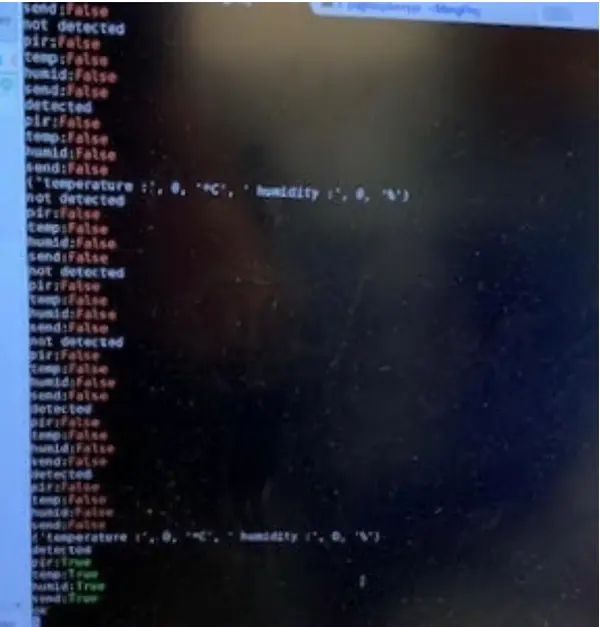
We connected the product to a PC via SSH, and it operated in sensing mode. Whenever the product detected something unusual, it promptly sent users an alarm email, as illustrated below:
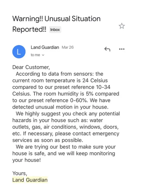
Initially, we configured the system to trigger an alarm email to residents under the following conditions: if the temperature exceeded 50 degrees Celsius or dropped below 15 degrees Celsius, if the humidity surpassed 60% or fell below 25%, or if the PIR motion sensor detected any movement. Throughout our one-week testing, we observed that the test results aligned with our planned criteria, validating the system's effectiveness.
Additionally, we initially set a minimum interval of 5 minutes between sending two consecutive alarm emails. As our equipment is designed for situations when the owner is not at home, we conducted the test in the doorway of our teammate Haodong Ping's room. During the one-week test, the PIR motion sensor triggered alarm emails precisely at the times Haodong Ping left for school and returned home. Alarm emails were also sent when Haodong Ping's roommate visited the room. However, no alarm emails were sent by the temperature and humidity sensor during the one-week test, as the temperature and humidity in a regular bedroom typically remain within a comfortable range.
To assess the temperature and humidity alarm capability, we configured the system with a maximum allowable room temperature of 8 degrees Celsius and a minimum temperature of 1 degree Celsius. During the 2-hour test, the system sent a total of 7 emails, indicating that it took approximately 15 minutes for the user to address the emergent situations at home upon receiving the alarm email. In our evaluation, this time interval is sufficient for residents to respond effectively. If the time interval were shorter, the user might receive numerous duplicate emails. Conversely, if the interval were longer, the system might not detect simultaneous theft events effectively.
Furthermore, we conducted testing to observe the behavior of the system when the WiFi connection was disabled. We powered off the WiFi for a period and tested whether the system would still trigger an alarm email if someone passed by the equipment. The result indicated that the alarm email was not sent when the WiFi was turned off.
Overall, the one-week test results of our equipment align with our expectations. However, we have also identified areas that require improvement, and we are committed to enhancing and perfecting our equipment in the future.