To begin, here are some introductory remarks:
I apologize for any shortcomings in my English. I hope to be easily understood by all readers, and if that's not the case, please feel free to ask any questions.
I wrote this tutorial when my project was nearly finished, so there is a possibility that I may have forgotten some steps or that certain reported steps may not work. Once again, please don't hesitate to ask for clarification.
I haven't included any SD image files in this tutorial, as I do not recommend accepting any images found on the web for such sensitive applications. The purpose of this tutorial is to enable you to create and customize your own image.
While I have been using Linux as my primary operating system at home for many years, I am not an expert sysadmin or a web developer by any means. If you have better methods for completing certain steps in this tutorial, I would greatly appreciate your suggestions on how to improve this project.
Now, let's commence with this tutorial.
In theory, it might even be feasible to add more camera modules. I have no doubt that you'll discover how to do so after reading this tutorial.
Firstly, let me present my specific requirements through a practical application: a dual baby monitor.
A few months ago, I became the fortunate father of twin daughters. Dealing with the challenges of having twins, I encountered difficulty in finding a suitable baby monitor that could monitor both of my babies simultaneously.
Being an absolute nerd and a Raspberry Pi enthusiast, I decided to resolve this frustrating issue using a Raspberry Pi and cameras. This approach also offered an intriguing possibility: utilizing a wired connection instead of the typical wireless link found in most baby monitors.
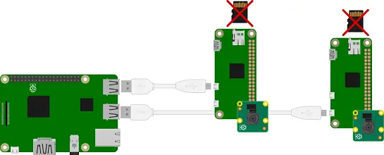
I explored numerous solutions before the outlandish idea struck me: attaching two official Raspberry Pi cameras to a Raspberry Pi 3… with a Raspberry Pi Zero in between!
The official camera enjoys excellent support and documentation, providing the necessary resources to complete my project on time! Additionally, the official case that houses the Pi Zero and the camera is aesthetically pleasing and perfectly suited for a child's room.
And, the icing on the cake: the Raspberry Pi Zero possesses a magical power that regular Pis lack—the ability to operate without a microSD card!
This forms the core of the current project and tutorial.
For this project, you'll have to acquire the following parts :
– A standard Raspberry Pi (3B, 3B+)
– Two Raspberry Pi NoIR cameras
– Two Raspberry Pi Zero boards (excluding the Zero W)
– Official cases for the Raspberry Pi and camera
– A high-quality and high-speed SD card (such as Evo+, Samsung Pro, or any other very fast option)
– An excellent power supply (preferably the official one)
– A set of micro USB cables with sufficient thickness to provide the required power
This tutorial primarily focuses on assembly and extensive configuration/system skills, with little to no requirement for soldering skills (*with the exception of IR illumination, which is necessary for night vision and may involve soldering. However, this tutorial does not cover that aspect. Pre-made parts for IR illumination are available).
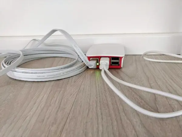
Now, let's take a look at the overview picture of the project:
The primary Raspberry Pi operates using its microSD card, which is flashed with the latest Raspbian (as of the time of writing, it is version 2018-11-13).
The microSD card also contains the images for the two attached Pi Zeros, which is why having a fast and reliable microSD card is crucial.
The key element in this setup is a mysterious tool developed by the Raspberry Pi Foundation called rpiboot (a link to this tool is provided at the end of the tutorial).
Using rpiboot, the Pi Zeros can boot up without the need for their own microSD cards. Instead, the necessary boot files and operating system are transferred to them via the USB cable during the startup process.
Once a Pi Zero is powered on and receives the necessary minimal files via the rpiboot utility, it is recognized as a USB to Ethernet gadget. This allows it to establish communication with the hosting Pi through a usbxx interface.
The root file systems (rootfs) of each Pi Zero are then shared using Network File System (NFS) and accessed through the emulated network interfaces (usb0/1/x).
This solution helps to keep costs down by eliminating the need for a microSD card for each Pi Zero. You only need to add a $5 Pi Zero for each camera you want to connect to your Pi.
However, implementing this solution requires several configuration steps, and we will go through each of them in this tutorial.
To begin this tutorial, it is assumed that you have a Raspberry Pi 3/3B(+) running with a fresh installation of Raspbian that is properly installed and fully functional.
Step I: Prepare the Pi Zero's remote images.
The original tutorial mentioned earlier recommends starting with a freshly downloaded Raspbian image. However, I chose an alternative approach: flashing a regular microSD card and using it to run a Pi Zero. This allowed me to perform all the necessary configurations (such as setting up the camera and enabling SSH at startup) and then retrieve the partition images from the microSD card.
While this method may be a bit tricky, it was the easiest option for me, especially regarding the configuration process (as I encountered difficulties in figuring out the SSH at startup issue). However, please note that this method requires having a spare microSD card dedicated to this purpose and a means of communication with your Pi Zero (such as a serial cable or a USB/Ethernet adapter).
Step I-1: Configure your Pi Zero with the following settings:
Code: Select all
$ sudo raspi-config
Navigate to “5 Interfacing Options” -> “P1 Camera” -> Select “Yes”
Navigate to “5 Interfacing Options” -> “P2 SSH” -> Select “Yes”
Navigate to “7 Advanced Options” -> “A3 Memory Split” -> Enter “256” -> Select “Ok”
Edit the config.txt :
Code: Select all
$ nano /boot/config.txtUncomment and edit the following line, in order to run the Pi Zero at 700 MHz
Code: Select all
#uncomment to overclock the arm. 700 MHz is the default.
arm_freq=700
Reducing arm frequency helps to save some power (don't forget both Pi Zeroes are powered by the main Raspberry Pi's USB ports), I tried lower values but 700 seems to be the best tradeoff.
Also add the following lines on the config.txt :
Code: Select all
dtoverlay=dwc2
initramfs initrd.img followkernel
Save the file and restart the Pi Zero. You should be able to log with ssh and verify the ARM frequency by :
Code: Select all
$ vcgencmd measure_clock arm
$ frequency(45)=700000000
Finally, you'll have to figure out an internet connection on your Pi Zero in order to install Picamera for Python packages (you need to be connected for that):
Code: Select all
$ sudo apt-get update
$ sudo apt-get install python-picamera python3-picamera
After this point, you won't have to boot up directly from your Pi zero.
Turn off your Raspberry Pi zero, remove the µSD card, and insert it on a USB or SD adapter in a regular Linux computer or even your Raspberry Pi (you'll need some disk space, though) for the next step.
I-2 Disk image tweaking
Insert the µSD on your Linux computer or Main Raspberry Pi (which IS a Linux computer indeed).
Type “dmesg” on terminal and find an output similar to this, with the device name apearing (“sda” in our case)
Code: Select all
[ 4927.859480] scsi host0: usb-storage 1-1.1.2:1.0
[ 4928.873892] scsi 0:0:0:0: Direct-Access     Generic- SD/MMC/MS PRO    1.00 PQ: 0 ANSI: 4
[ 4928.893853] sd 0:0:0:0: Attached scsi generic sg0 type 0
[ 4929.508361] sd 0:0:0:0: [sda] 30703616 512-byte logical blocks: (15.7 GB/14.6 GiB)
Type the following command to confirm both µSD's partitions :
Code: Select all
$ ls /dev/sda*
/dev/sda  /dev/sda1  /dev/sda2
The boot partition is on /dev/sda1 and the rootfs is on /dev/sda2.
Next, we'll make an image of both partitions (caution : the second dd is time and disk space hungry) :
Code: Select all
$ sudo dd if=/dev/sda1 of=boot.img
89854+0 records in
89854+0 records out
46005248 bytes (46 MB, 44 MiB) copied, 1.53241 s, 30.0 MB/s

$ sudo dd if=/dev/sda2 of=rootfs.img
30605312+0 records in
30605312+0 records out
15669919744 bytes (16 GB, 15 GiB) copied, 1511.61 s, 10.4 MB/s
As you can see, the image has the size of the whole µSD card. This is why this process is quite disk space hungry. Let's shrink this disk image to a reasonable size.
Code: Select all
$ sudo truncate --size=3G rootfs.imgAfter that, verify the image size :
Code: Select all
$ ls -lh rootfs.img
-rw-r--r-- 1 root root 3.0G Dec 10 19:49 rootfs.img
CAUTION: never truncate a disk image without knowing exactly how much free space is remaining on it ! Verify if needed by a “df -h” command !
I first ran the fdisk utility to reduce partition size before truncating it, but it doesn't seems to be necessary.
Finaly, duplicate those images, since we need one image for each Pi Zero.
Code: Select all
$ mv boot.img boot1.img
$ cp boot1.img boot2.img
$ mv rootfs.img rootfs1.img
$ cp rootfs1.img rootfs2.img
I-3 Prepare directories and mounting scripts
We need to have one directory for boot and another for the rootfs, for each Pi Zero :
Code: Select all
$ mkdir boot
$ mkdir boot/1-1.3
$ mkdir boot/1-1.2
$ mkdir root1
$ mkdir root2
The naming scheme for the boot directory is quite special: it relates to the physical USB port. So you'll have to connect each Pi Zero on the correct port (on Pi 3B they are the two ports next to the Ethernet port, and on 3B+ they are the two ports on the right).
Edit the following mounting script :
Code: Select all
$ nano mount.shCode: Select all
#!/bin/sh
/bin/mount -o loop /home/pi/boot1.img /home/pi/boot/1-1.3
/bin/mount -o loop /home/pi/boot2.img /home/pi/boot/1-1.2
/bin/mount -o loop /home/pi/rootfs1.img /home/pi/root1
/bin/mount -o loop /home/pi/rootfs2.img /home/pi/root2
Make this script executable by :
Code: Select all
$ chmod +x mount.shLet's test this mounting script, we'll need those images mounted for the next configuration step :
Code: Select all
$ ./mount.shTo verify, you can type :
Code: Select all
$ df -hAnd you can see those lines :
Code: Select all
/dev/loop0       44M   29M   15M  67% /home/pi/boot/1-1.3
/dev/loop1       44M   29M   15M  67% /home/pi/boot/1-1.2
/dev/loop2      3.0G  1.2G  1.7G  42% /home/pi/root1
/dev/loop3      3.0G  1.2G  1.7G  42% /home/pi/root2
It means that everything worked as expected.
I-4 Create the initramfs
On the main Pi, run:
Code: Select all
$ sudo apt install initramfs-toolsEdit modules in initramfs:
Code: Select all
$ sudo nano /etc/initramfs-tools/modulesCode: Select all
g_ether
libcomposite
u_ether
udc-core
usb_f_rndis
usb_f_ecm
Then type:
Code: Select all
$ uname -rcopy-paste the kernel version, removing the “-v7” suffix in the following command:
Code: Select all
$ sudo update-initramfs -c -k "version_returned_without_v7_suffix"In my version, it gives :
Code: Select all
$ sudo update-initramfs -c -k "4.14.79+"Copy the initramfs :
Code: Select all
$ sudo cp /boot/initrd.img-4.14.79+ /home/pi/boot/1-1.3/initrd.img
$ sudo cp /boot/initrd.img-4.14.79+ /home/pi/boot/1-1.2/initrd.img
I-5 Finalize
We need some extra configuration of the cmdline.txt for each Pi Zero, for network and nfs configuration:
Pi Zero 1:
Code: Select all
$ nano boot/1-1.3/cmdline.txtEdit in one single line (VERY important) in order to have this, exactly:
Code: Select all
dwc_otg.lpm_enable=0 console=serial0,115200 console=tty1 root=/dev/nfs nfsroot=192.168.1.254:/home/pi/root1 rw ip=192.168.1.1:192.168.1.254::255.255.255.0:::static elevator=deadline modules-load=dwc2,g_ether fsck.repair=yes rootwait
Pi Zero 2:
Code: Select all
$ nano boot/1-1.2/cmdline.txtAs above, edit in one single line in order to have this, exactly:
Code: Select all
dwc_otg.lpm_enable=0 console=serial0,115200 console=tty1 root=/dev/nfs nfsroot=192.168.2.254:/home/pi/root2 rw ip=192.168.2.1:192.168.2.254::255.255.255.0:::static elevator=deadline modules-load=dwc2,g_ether fsck.repair=yes rootwaitWe also need to tweak the original mounting configuration file of each Pi Zero, to avoid mounting the boot/rootfs on the missing µSD card, and to mount the boot partition remotely, by nfs:
Pi Zero 1:
Code: Select all
$ nano /root1/etc/fstabCode: Select all
proc            /proc           proc    defaults          0       0
192.168.1.254:/home/pi/boot/1-1.3       /boot   nfs     defaults        0       0
#PARTUUID=f38c7dd9-01  /boot           vfat    defaults          0       2
#PARTUUID=f38c7dd9-02  /               ext4    defaults,noatime  0       1
# a swapfile is not a swap partition, no line here
#   use  dphys-swapfile swap[on|off]  for that
Pi Zero 2:
Code: Select all
$ nano /root2/etc/fstabCode: Select all
proc            /proc           proc    defaults          0       0
192.168.2.254:/home/pi/boot/1-1.2       /boot   nfs     defaults        0       0
#PARTUUID=f38c7dd9-01  /boot           vfat    defaults          0       2
#PARTUUID=f38c7dd9-02  /               ext4    defaults,noatime  0       1
# a swapfile is not a swap partition, no line here
#   use  dphys-swapfile swap[on|off]  for that
Step II: Prepare the Main Raspberry Pi
II-1 rpiboot
Just follow the instructions on the official github:
https://github.com/raspberrypi/usbboot
Code: Select all
$ git clone --depth=1 https://github.com/raspberrypi/usbboot
$ cd usbboot
$ sudo apt-get install libusb-1.0-0-dev
$ make
Let's include the proper command in an executable script :
Code: Select all
$ nano rpiboot.shCode: Select all
#!/bin/sh
/home/pi/usbboot/rpiboot -d /home/pi/boot/ -o -l
Code: Select all
$ chmod +x rpiboot.shII-2 Make it all run at statup with rc.local
Code: Select all
$ nano /etc/rc.localCode: Select all
#!/bin/sh -e
#
# rc.local
#
# This script is executed at the end of each multiuser runlevel.
# Make sure that the script will "exit 0" on success or any other
# value on error.
#
# In order to enable or disable this script just change the execution
# bits.
#
# By default this script does nothing.

# Print the IP address
_IP=$(hostname -I) || true
if [ "$_IP" ]; then
  printf "My IP address is %s\n" "$_IP"
fi
/usr/bin/tvservice -o
/home/pi/mount.sh
/home/pi/rpiboot.sh
exit 0
Yes, I added a “tvservice -o” to draw a little less power here too.
II-3 Network configuration
In Raspbian Stretch, the network configuration file not seem to be /etc/network anymore, but /etc/dhcpcd.conf.
Add the following lines in this configuration file:
Code: Select all
$ sudo nano /etc/dhcpcd.confCode: Select all
interface usb0
static ip_address=192.168.1.254

interface usb1
static ip_address=192.168.2.254
This will make static separate networks for our 2 Pi Zero once they will be online (very important).
II-4 NFS
In order to allow the Pi Zeroes to access to their rootfs and boot partitions, you must install NFS and edit the appropriate configuration file:
Code: Select all
$ sudo apt install nfs-kernel-serverCode: Select all
# /etc/exports: the access control list for filesystems which may be exported
#               to NFS clients.  See exports(5).
#
# Example for NFSv2 and NFSv3:
# /srv/homes       hostname1(rw,sync,no_subtree_check) hostname2(ro,sync,no_subtree_check)
#
# Example for NFSv4:
# /srv/nfs4        gss/krb5i(rw,sync,fsid=0,crossmnt,no_subtree_check)
# /srv/nfs4/homes  gss/krb5i(rw,sync,no_subtree_check)
#
/home/pi/root1 192.168.1.1(rw,sync,fsid=0,insecure,no_subtree_check,no_root_squash)
/home/pi/root2 192.168.2.1(rw,sync,fsid=0,insecure,no_subtree_check,no_root_squash)
/home/pi/boot/1-1.3 192.168.1.1(rw,sync,insecure,no_subtree_check,no_root_squash)
/home/pi/boot/1-1.2 192.168.2.1(rw,sync,insecure,no_subtree_check,no_root_squash)
Restart the NFS service:
Code: Select all
$ sudo systemctl restart nfs-server.service
$ sudo exportfs -a
II-4 Nginx
As usual, a hosted web page will allow viewing both video streams. But we have another key requirement that nginx can cover particulary well.
As we have 2 separated networks (192.168.1.1 and 192.168.2.1) for a unique public address reachable from our local network, we have to route each stream to the end user.
I first tried to achieve this with iptables but it was a nightmare. Fortunately, Nginx offers the functionnality I need : the “proxy_pass” feature !
First, you have to install the nginx server:
Code: Select all
$ sudo apt-get install nginxThen, edit the current default enabled site configuration file :
Code: Select all
$ sudo nano /etc/nginx/sites-enabled/defaulton the “server { }” section, search the “location / {” section and add just after both Pi zeroes location, like this :
Code: Select all
location / {

# First attempt to serve request as file, then

# as directory, then fall back to displaying a 404.

try_files $uri $uri/ =404;

}
location /camera1/ {

proxy_pass http://192.168.1.1:8000/;

}
location /camera2/ {

proxy_pass http://192.168.2.1:8000/;

}
# First attempt to serve request as file, then
# as directory, then fall back to displaying a 404.
try_files $uri $uri/ =404;
}
location /camera1/ {
proxy_pass http://192.168.1.1:8000/;
}
location /camera2/ {
proxy_pass http://192.168.2.1:8000/;
}
II-5 Scripts and website
Streaming video from the Pi Zeroes:
To begin, you need to decide how you want to provide the video stream. I came across several solutions, such as cvlc, mjpegstreamer, and raspivid, among others.
However, there is something peculiar: H264 offers better efficiency, but if you want compatibility with most web browsers, you'll have to use the MJPEG format.
Therefore, the solution is to utilize a Python script that incorporates the excellent picamera library. You can find the script at the following link:
https://picamera.readthedocs.io/en/rele … -streaming
I made modifications to this script to align with my specific requirements, including the desired video mode.
Code: Select all
import io
import picamera
import logging
import socketserver
from threading import Condition
from http import server
import datetime as dt
import threading

PAGE="""\
<html>
<head>
<title>Camera MJPG Stream</title>
</head>
<body>
<img src="stream.mjpg" width="1280" height="720" />
</body>
</html>
"""

class StreamingOutput(object):
    def __init__(self):
        self.frame = None
        self.buffer = io.BytesIO()
        self.condition = Condition()

    def write(self, buf):
        if buf.startswith(b'\xff\xd8'):
            # New frame, copy the existing buffer's content and notify all
            # clients it's available
            self.buffer.truncate()
            with self.condition:
                self.frame = self.buffer.getvalue()
                self.condition.notify_all()
            self.buffer.seek(0)
        return self.buffer.write(buf)

class StreamingHandler(server.BaseHTTPRequestHandler):
    def do_GET(self):
        if self.path == '/':
            self.send_response(301)
            self.send_header('Location', '/index.html')
            self.end_headers()
        elif self.path == '/index.html':
            content = PAGE.encode('utf-8')
            self.send_response(200)
            self.send_header('Content-Type', 'text/html')
            self.send_header('Content-Length', len(content))
            self.end_headers()
            self.wfile.write(content)
        elif self.path == '/stream.mjpg':
            self.send_response(200)
            self.send_header('Age', 0)
            self.send_header('Cache-Control', 'no-cache, private')
            self.send_header('Pragma', 'no-cache')
            self.send_header('Content-Type', 'multipart/x-mixed-replace; boundary=FRAME')
            self.end_headers()
            try:
                while True:
                    with output.condition:
                        output.condition.wait()
                        frame = output.frame
                    self.wfile.write(b'--FRAME\r\n')
                    self.send_header('Content-Type', 'image/jpeg')
                    self.send_header('Content-Length', len(frame))
                    self.end_headers()
                    self.wfile.write(frame)
                    self.wfile.write(b'\r\n')
            except Exception as e:
                logging.warning(
                    'Removed streaming client %s: %s',
                    self.client_address, str(e))
        else:
            self.send_error(404)
            self.end_headers()

class StreamingServer(socketserver.ThreadingMixIn, server.HTTPServer):
    allow_reuse_address = True
    daemon_threads = True

with picamera.PiCamera(sensor_mode=5, framerate=24) as camera:
    output = StreamingOutput()
    camera.annotate_background = picamera.Color('black')
    camera.annotate_text = "CAMERA 1"
    camera.annotate_text_size = 16
    camera.start_recording(output, format='mjpeg', resize=(1280,720))
    try:
        address = ('', 8000)
        server = StreamingServer(address, StreamingHandler)
        server.serve_forever()
    finally:
        camera.stop_recording()
Copy this file, from your main Pi 3 on root1/home/pi and root2/home/pi
Modify the Pi zeroes rc.local in order to stream straight from a boot :
Code: Select all
$ nano root1/etc/rc.localCode: Select all
_IP=$(hostname -I) || true
if [ "$_IP" ]; then
  printf "My IP address is %s\n" "$_IP"
fi
/usr/bin/tvservice -o
/usr/bin/python3 /home/pi/stream.py
exit 0
(don't forget the “tvservice -o” again…)
Repeat for the second Pi Zero :
Code: Select all
$ nano root2/etc/rc.local Web Site on Main Pi 3:
Here after, the web site to put on a file named “index.html” on “/var/www/html/”:
Code: Select all
<html>
<head>
<meta name="viewport" content="width=device-width, initial-scale=1.0">
<style>
img {
  width: 50%;
  height: auto;
}
</style>
<title>Dual Pi Camera MJPEG Monitor Streaming</title>
</head>
<body>
<a href="camera1/index.html"><img src="camera1/stream.mjpg" width="1280" height="720" alt="Camera 1" border=0 /></a><a href="camera2/index.html"><img src="camera2/stream.mjpg" width="1280" height="720" alt="Camera 2" border=0 /></a>
</body>
</html>
Obviously, this site must be improved in the future. It's mostly for testing purposes.
Step III: Miscellaneous
III-1 Remote safe shutdown
Ensuring a safe shutdown process for both the Pi Zero and the main Raspberry Pi is of utmost importance. I am currently in the process of testing various solutions and will publish a recommended method once it is finalized.
My current approach involves sending remote “sudo halt” commands to both the Pi Zeroes before initiating the shutdown process on the main Raspberry Pi. However, I do not currently have a definitive method for accomplishing this. Rest assured, I will share the solution as soon as it is developed.
III-2 IR illuminator
As mentioned earlier, pre-made IR illuminators are readily available on the market. However, I decided to create my own.
My plan is to utilize the spare power micro USB port to connect a custom-made IR illuminator. Unfortunately, I have not yet received all the necessary components for this. I intend to use two IR 850nm LEDs connected in series with a resistor, which should provide sufficient illumination (taking into consideration power consumption and the proximity of the subjects).
III-3 Room's temperature/humidity
It is crucial to prioritize safety in a baby's room. To ensure the temperature measurements are accurate and to maintain a safe distance from the heat generated by the Pi 3B(+), I intend to utilize a Si7021 sensor with a few centimeters of wire. This will help keep the sensor positioned away from the heat source while still providing accurate temperature readings.
Step IV: Test it out !
IV-1 Linking them together
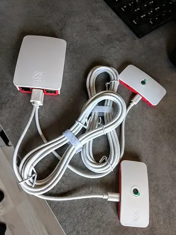
I opted for a 3-meter USB cable with the hope that it would be sufficient to transmit the required power over such a distance. Fortunately, it worked well (although I still need to test it with the IR illuminator).
Now, you can proceed by connecting the power supply and the Ethernet cable to your Raspberry Pi. You can then check if everything is functioning properly by accessing the Raspberry Pi's IP address using your preferred web browser.
Once you have established an SSH connection to your main Pi, you can verify that both USB connections (192.168.1.1 and 192.168.2.1) have been created for each Pi Zero.
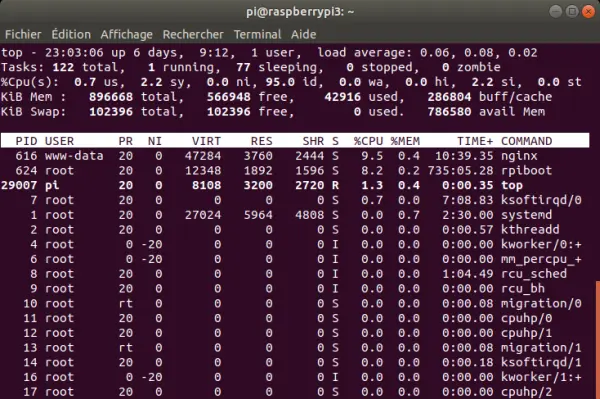
To assess the CPU and RAM usage during streaming, you can monitor the nginx line for each connection. Typically, the CPU usage for the first connection should be around 10-20%, with a slight increase for additional connections on the main Pi. The Rpiboot utility should consume up to 9% of CPU usage.
On the Pi Zero, you should observe only a “python3” line indicating the running script, which should utilize approximately 40-45% of the CPU. However, this percentage can increase to 80-90% when multiple connections are established (although it is not intended to be streamed globally in this particular use case). It is important to note that there is room for improvement in optimizing CPU usage for multiple connections.
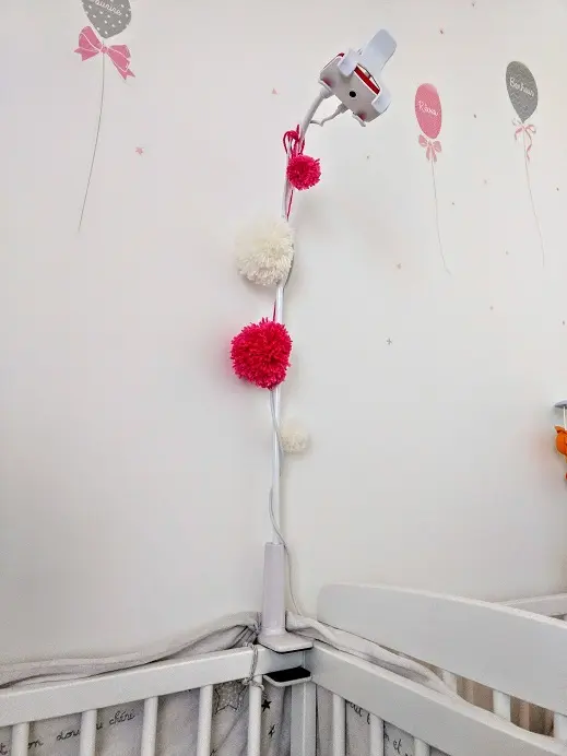
IV-2 Placing the whole configuration in real conditions

SSH on the Pi 3 and one Pi Zero, showing a top's result