
In this instructional guide, we will initially explore the functioning of switches and the various types of switches suitable for your projects. Subsequently, we will demonstrate how to effectively utilize these buttons and switches on the Raspberry Pi. Let's commence our journey

HOW A SWITCH WORKS
Let's illustrate the concept of a switch using an analogy with a water tap. Similar to how a tap controls the flow of water, switches act as valves in the engineering domain. When a tap is opened, water flows, and when it is closed, the water flow is restricted. In the realm of electronics, we can apply the same idea: envision the water as the current or the movement of electrons, and the switch as the tap or valve that regulates the current flow.
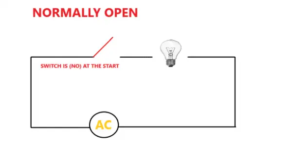
Typically, most switches are in the normally open (NO) state, meaning that the circuit connected to the switch is not linked to the power supply when the switch is open. Unless the switch is pressed, the circuit remains in that position.

Let's incorporate a normally open switch into a circuit. Here we have a bulb connected to the AC supply through a NO switch. The bulb will remain unlit until the switch is closed.
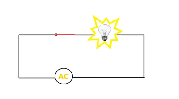
When the switch is pressed, the circuit becomes connected, resulting in the bulb illuminating.
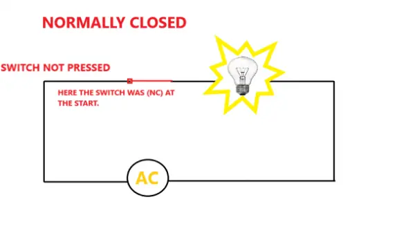
Another type of switch is known as the normally closed switch (NC), which operates in the opposite manner. While normally closed switches are not commonly used in electronics, they are commonly employed in electrical applications such as power control and process control systems.
Below is a circuit diagram depicting a bulb connected to the AC supply through a normally closed switch. It is important to observe that the circuit is already closed, allowing the bulb to receive power from the AC mains. The switch remains closed until it is pressed or activated. When the button of this normally closed switch is pressed, the circuit will be interrupted, preventing any current from flowing to the light bulb. Typically, normally closed switches function in an opposite manner to normally open switches, and as a result, they find widespread use in various industrial electrical applications involving contactors and relays.
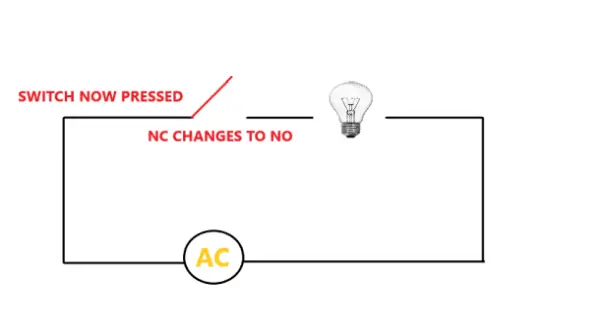
The picture below shows the circuit after the button is pressed.
POLES AND THROWS
The poles and throws are crucial components of a switch. When utilizing a switch for your project, it is important to determine the number of individual circuits you intend the switch to control and whether you require simultaneous control over multiple channels. Therefore, comprehending the pole and throw specifications of each switch type becomes necessary.
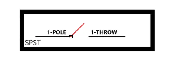
The term “pole” refers to the number of circuits that can be connected and controlled by a switch. For instance, a single-pole switch can manage the on/off operation of a single circuit, while a three-pole switch can govern three circuits, and so forth. On the other hand, the term “throw” signifies the number of positions to which a pole can connect within the switch. For a more comprehensive exploration of these concepts, we recommend referring to our Complete Guide to Electronic Switches article.
Here is a schematic diagram of a single pole, single throw (SPST) switch:
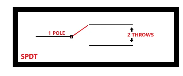
There are other switches as well like SPDT (single pole, double throw) and DPDT (double pole, double throw):
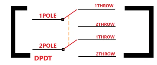
Upon careful observation of the DPDT switch, you may notice the presence of an orange dotted line positioned between the poles. This line indicates that when the switch is pressed or activated, both poles undergo a simultaneous and synchronized transition from the first throw to the second throw.
Having familiarized ourselves with the fundamental aspects of switches, we can now delve into exploring the various types of switches suitable for our projects.
TYPES OF SWITCHES
There exist three primary categories of switches:
- Mechanical switches: These switches are frequently employed in households for controlling various appliances such as televisions, light bulbs, and fans.
- Electronic switches: These switches find extensive usage in solid-state circuits, enabling the switching of devices based on electronic input signals.
- Integrated sensors: These switches are utilized when a device needs to be activated or deactivated in response to readings from a sensor. Integrated with sensors, these switches can perform actions such as turning on a fan when a temperature sensor detects a rise in temperature.
MECHANICAL SWITCHES
Switches that necessitate human interaction are referred to as mechanical switches. In basic terms, the operation of these switches relies on actions such as pressing, pulling, pushing, or releasing, which enable the activation or deactivation of a specific circuit.
There are several distinct types of mechanical switches, including:
- Push buttons
- Toggle switches
- Rotary switches
- Slide switches
- DIP switches (Dual In-line Package switches)
- Limit switches
PUSH BUTTONS
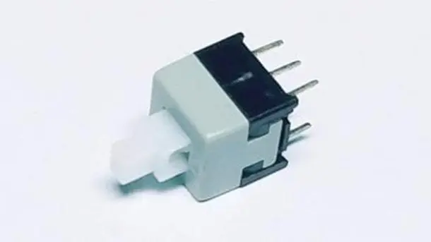
The commonly employed switch in electronic applications is the push-button switch. These SPST (Single-Pole, Single-Throw) push-button switches enable the circuit to be either completed or interrupted with a straightforward push action. Typically, they are available in the normally open (NO) configuration.
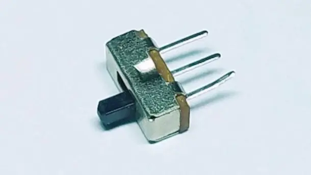
TOGGLE SWITCHES

Toggle switches are designed to establish or interrupt a circuit by vertically moving a lever either up or down. They are available in various configurations, including SPST (Single-Pole, Single-Throw), SPDT (Single-Pole, Double-Throw), and DPDT (Double-Pole, Double-Throw). Certain toggle switches are equipped with an off position located at the center, allowing the circuit to be activated by moving the lever either upwards or downwards.
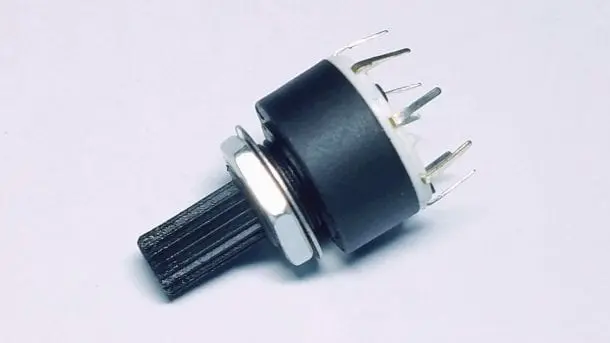
ROTARY SWITCHES
Slide switches are utilized to activate or deactivate a circuit by means of a sliding mechanism. By default, the slider is positioned in a normally open state. However, once the slider is moved from one position to another, the circuit establishes a connection with the power supply. Slide switches commonly come in SPDT (Single-Pole, Double-Throw) configuration, although other configurations are also available.
DIP SWITCHES
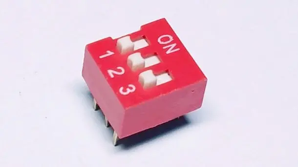
DIP switches are compact devices that incorporate multiple individual switches within a single package. These switches function in a similar manner to slide switches, but their initial configuration is consistently SPST (Single-Pole, Single-Throw). DIP switches are commonly employed in low voltage and current applications.
LIMIT SWITCHES
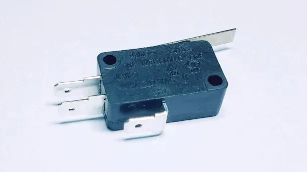
Limit switches find application in machinery and industrial settings, where the motion of an object can actuate the lever connected to the switch.
ELECTRONIC SWITCHES
Electronic switches are constructed using semiconductor materials and do not rely on human interaction to function. An example of such a switch is a transistor, which, when supplied with sufficient current at the base, completes the circuit between the emitter and collector.
Various types of electronic switches include:
- Bi-Polar Junction Transistors (BJT)
- Metal oxide semiconductor field-effect transistors (MOSFET)
- Insulated-gate bipolar transistors (IGBT)
Transistors can be employed in both low-power and high-power circuit applications. They are capable of rapid switching at specific frequencies, depending on the intended use of the transistor.
BI-POLAR JUNCTION TRANSISTORS
Bi-polar junction transistors (BJTs) can function as switches when biased in the saturation or cut-off regions. In this context, they are often referred to as current-controlled devices, as the base current governs their operation.
METAL OXIDE SEMICONDUCTOR FIELD-EFFECT TRANSISTORS
Metal oxide semiconductor field-effect transistors (MOSFETs) serve as both switches and amplifiers for small electronic signals. While they are commonly employed as amplifiers due to their high input impedance, which allows them to effectively capture low signals, MOSFETs can also function as switches. When utilizing MOSFETs as switches, it is important to consider their operating state, which lies between the cutoff and saturation regions. MOSFETs are classified as voltage-controlled devices.
INSULATED-GATE BIPOLAR TRANSISTORS
Insulated-gate bipolar transistors (IGBTs) are preferred for their ability to facilitate fast switching. Consequently, they find application in switching amplifiers within audio amplifier circuits and industrial control systems. IGBT transistors possess higher current and voltage ratings compared to most MOSFETs. However, their switching speed is generally slower in comparison.
Now, let's proceed to construct a sample project that can detect the on/off state of an SPST toggle switch in order to control an LED.
HOW TO USE A TOGGLE SWITCH ON THE RASPBERRY PI
Toggle switches are the most frequently encountered type of switch in various projects. They are available in SPST, SPDT, or DPDT configurations. In this tutorial, we will conduct a practical demonstration utilizing a Raspberry Pi to illuminate an LED using an SPST toggle switch.
COMPONENTS REQUIRED
For this project, you will need the following components:
- Raspberry Pi
- SPST toggle switch
- One LED
- Jumper wires
- 220 Ohm resistor
- Breadboard
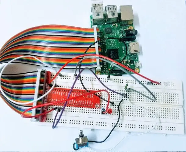
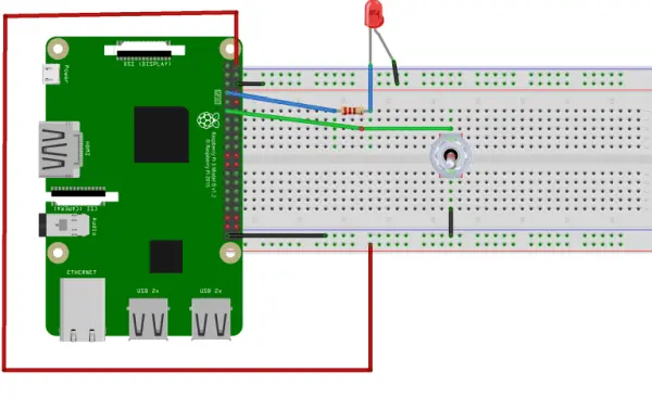
To begin, follow the wiring diagram provided below to establish the connections. If you decide to connect the LED and switch to different GPIO pins, make sure to update the corresponding pin numbers in the Python code.
THE CODE
The following Python code is a program for this project. Simply copy the code and paste it into the Nano text editor. Save the file as “LED.py”.
# import the libraries
import RPi.GPIO as GPIO
from time import sleep
GPIO.setmode(GPIO.BCM)
# set the pin numbers to be used from Broadcom chip
ledpin = 4 # assign a variable name to pin 4
pushpin = 17 # assign a variable name to pin 17
GPIO.setup(ledpin, GPIO.OUT) # set GPIO pin 4 as Output
GPIO.setup(pushpin, GPIO.IN) # set GPIO pin 17 as Input
GPIO.setup(4, GPIO.OUT, initial=GPIO.LOW) # set the initial output of pin 4 to be LOW
while True:
GPIO.output(ledpin, not GPIO.input(pushpin)) # read the inverse value of input pin 17
sleep(0.2)
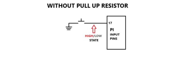
To execute the aforementioned code, enter “sudo LED.py” on the command line. Once the code is running, toggle the switch to the “on” position and observe the outcome. However, you may encounter a common issue where the LED either blinks erratically or fails to illuminate. This issue arises due to floating pins, a problem encountered by most microcontrollers. To resolve this problem, we need to incorporate a pull-up resistor into the circuit.
FLOATING PINS AND PULL-UP RESISTOR
Typically, when connecting a switch to boards like the Raspberry Pi, the switch is susceptible to continuous interference from nearby electromagnetic waves. This interference can disrupt the intended behavior of the switch, causing issues when transitioning between the HIGH and LOW states of the pin. In certain cases, the switch may even fail to function properly.
To address this problem, we employ a pull-up resistor. By incorporating a pull-up resistor, we establish a stable state for pin 17. This is achieved by connecting the resistor to the positive supply, effectively grounding the input state and maintaining it at a HIGH level until the switch is pressed.
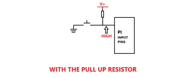
Observe the manner in which the resistor is connected to the toggle switch. On one end, it is linked to the positive supply, while on the other end, it is connected to a single wire that is shared by both pin 17 and the toggle switch.
CODE FOR CIRCUIT WITH A PULL-UP RESISTOR
#Importing the Right libraries
import RPi.GPIO as GPIO
from time import sleep
GPIO.setmode(GPIO.BCM)
ledpin = 4
pushpin = 17
GPIO.setup(ledpin, GPIO.OUT)
GPIO.setup(pushpin, GPIO.IN, pull_up_down=GPIO.PUD_UP) # using the internal Pull up resistor
GPIO.setup(4, GPIO.OUT, initial=GPIO.LOW)
while True:
GPIO.output(ledpin, not GPIO.input(pushpin)) # Reading the inverse value of input pin 17
sleep(0.2)
To implement the instructions above, please follow these steps:
- Copy and paste the provided code into a new file in the Nano text editor.
- Save the file with the name “LED.py”. You can choose any other name, but ensure to include the .py extension.
To run the code, enter “sudo LED.py” in the command line. When you toggle the switch, you will observe that the LED turns on and off accordingly.
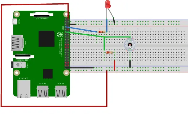
As previously mentioned, an alternative method to include a pull-up resistor is by utilizing an external pull-up resistor in the circuit. Refer to the wiring diagram below to understand how the external pull-up resistor is incorporated into the existing circuit.
[Insert wiring diagram here]
Ensure you make the necessary connections as shown in the diagram to complete the circuit with the external pull-up resistor.
Alternatively, you have the option to utilize a pull-down resistor, which functions in the opposite manner. However, for the time being, let's concentrate solely on the implementation of a pull-up resistor.
Now, let's proceed with another project example, this time employing a tactile switch instead of a toggle switch.
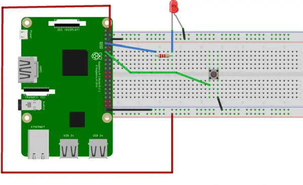
HOW TO USE A TACTILE PUSH BUTTON ON THE RASPBERRY PI
For this particular project example, we will employ a tactile push button in conjunction with a pull-up resistor to regulate the behavior of an LED.
In this project, the LED will be initially in the ON state. However, by pressing the push button, the LED will be switched to the OFF state.
THE CODE
import RPi.GPIO as GPIO
from time import sleep
GPIO.setmode(GPIO.BCM)
ledpin = 4 # set output LED pin
pushpin = 17 # set input push button pin
GPIO.setup(ledpin, GPIO.OUT) # set ledpin as an output
GPIO.setup(pushpin, GPIO.IN, pull_up_down=GPIO.PUD_UP) # with pull up resistor
while True:
GPIO.output(ledpin, GPIO.input(pushpin))
sleep(0.2)