
For a while now, I wanted to create a children's toys, but with a tech-twist.
As a first take in the field, thought it would be interesting to do something related to those old-school farm animal sound toys. I am talking about the ones with the animals lined up and concealed, press a big plastic button and the corresponding animal would pop up and make the animal's sound. Now that's nice and all, but very limited.
The newly designed version will boast some additional features. After all, I need to justify the use of a Rpi 😉
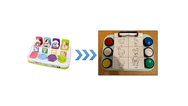
The new and improved version features six LED big arcade buttons with a printed card slip in the middle. The card has a nice secret inside, an RFID tag. The toy casing holds the RFID reader, and as you have probably figured out by now, will change the set of sounds the toy can generate as a function of which card is being mounted on the toy.
The current version includes:
- On-the-fly change of cards to change sound sets
- Auto sleep for battery saving
- Auto boot-up
- boot-up, sleep, and shut-down audio-visual notifications
- Multiple sounds for each button pressed (randomizes from different sounds of the same animal/other)
- 5 sound sets, easily introduce more
Future versions will include
*This project was not that well documented with photos from day 1 but its quite straight-forward and simple. If you have any questions, PM me.
Supplies
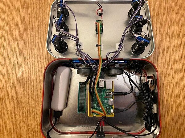
- A project box (I used a metallic chocolates box)
- A wooden plate (only if you use metallic box so that the RF will penetrate the box)
- 5V USB powered speaker(s) w/built-in amplifier and 3.5m jack (the cheap stuff is the best)
- Raspberry pi
- Some jumper wires, pins, and connectors
- prototype “naked” PCB for collecting GND wires
- ON/OFF 5V toggle button
- 5V powerbank with a USB-microUSB cable
- 6 x ‘arcade style' LED pushbuttons
- Cable holders and zip-ties
- RDM6300 RFID reader
- flat coin-sized RFID tags (at least 4)
- Binder clip
I like to have a box, either a big one or with small compartments to hold all my project parts so they don't get lost (a project might take weeks or months and things have a tendency to disappear).
Beginning with the pushbuttons, mine came with LEDs so there are three connections to be made:
- GND (-)
- 5V (+) for the LED
- 5V (+) for the button I/O signal
I have connected all GND into a single bundle to then connect that with a single wire to the common ground of the Rpi.
Make sure to “measure twice and cut once” so you don't have too short or too long wires.
Step 2: Prepare the Speakers
If you have opted to make your own speaker system from individual components (speaker, amplifier, etc.) you can skip this step. Most speakers come with some sort of enclosure. depending on your packaging of the project components, I recommend removing all excess plastic packaging of the speakers to make it easier to package inside our project box.
You should end up with just the bare-bone speakers (basically the magnet and membrane), amplifier (about the size of half a match box), and some thin wires for power and signal
Step 3: Connect Everything to the Raspberry Pi
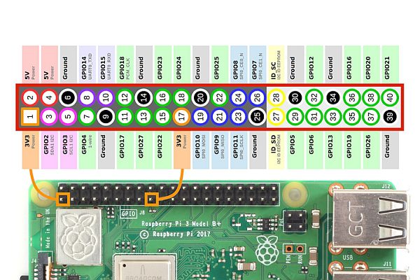
Crimp your wire ends with connectors and connect following this pinout:
# --------Pinout----------
# Green LED     26
# Green button  19
# White LED     13
# White button  6
# White2 LED    7
# White2 button 8
# Red LED       5
# Red button    11
# Blue LED      21
# Blue button   20
# Yellow LED    16
# Yellow button 12
# Common ground GND
# --------------------------
To connect the RFID reader module, follow the this blog post
Next, connect the 3.5mm headphone jack to the ‘Audio Out' jack of the Raspberry pi.
Finally, connect the power-bank to the toggle switch:
- Cut the USB cable, the only needed wires are the power lines (Vcc and GND)
- Connect the GND to the common ground of the Raspberry pi
- Solder the Vcc of each side of the USB to each pole of the toggle
Finish off with connector crimps and wire insulation (I like working with heat shrinks) at the wire endpoints where possible. A good looking work is usually a good working assembly.
*Recommend “beeping” with a multimeter to make sure there are no short-circuits or open connections BEFORE connecting power.
Step 4: Modify RFID Tag UIDs
Download the project source code and files from the Github repository
In the ‘keyboard.py' file, change the lines corresponding to your tag's UID
RFreader = rdm6300.Reader('/dev/ttyAMA0') #Initialize rfid card reader
currentCard = 0
cardSets = {
7646102 :  [cow, sheep, chicken, horse, duck, pig],
9819485 : [lion, elephant, monkey, bear, hawk, dolphin],
9811477 : [train, plane, car, tractor, bicycle, race_car],
9787282 : [piano, guitar, violin, trumpet, drum]}
Each tag is identified by a 7-digit ID number. Usually these numbers are written on the tags themselves. If not, you can always program the RFID quickly with a reader example in the RDM6300 library, read the tags, and print their UID on the terminal. Write down their UID and replace in the code above.
Each tag number is associated with a sound library.
If you want to add libraries, simply add a python dictionary with six entries. Make sure you add .wav file paths in the ‘soundPaths.py' file, and the sound files in the corresponding folder.
Step 5: Program the Raspberry Pi
Make sure your Raspberry pi is running the latest Raspbian OS
Connect the Raspberry pi to your PC (or SSH it) and upload the entire repository to a folder on the Raspberry pi SD card
Make ‘keyboard.py' run on boot using one of these methods (some worked for me and some didn't, pick what suits)
Step 6: Making It Work Out of the Box (literally)
Before we go beyond the ‘point of no return' and start making holes in the box and putting everything together, we need to do a dry run.
Connect the MicroUSB cable to power the Rpi and test out the system. If everything works, that's great!
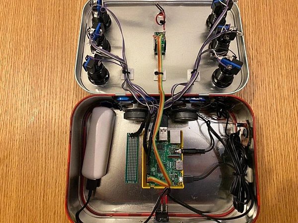
Step 7: Package Everything in the Project Box
Drill holes for the six pushbuttons, a good way to do this is with a conical drill bit. Start off with a regular small diameter (~3mm) drill to make a pilot hole and follow through with the conical. Install the pushbuttons.
Next, drill a small hole to pass the RFID reader's coil wires. On the inside of the box glue the reader module (the circuit), and on the outside, glue the coil. Do this on the place you plan to have the sound card with the drawings. I covered my coil with a piece of thin wood to make it look nice and be more durable.
NOTE: If your box is made of plastic/wood/any non-metallic material, odds are you can simply glue the coil on the inside as well.
Drill small (~2-3mm) holes for the speaker sound to be heard, and glue or bolt the speakers on the inside of the box.
Drill a cut-out for the power toggle switch and mount that as well.
Glue the binder clip the the top of the box lid to be able to hold the sound cards.
Finally, mount the power-bank, PCB, and Rpi. I used double-sided tape. Nice and easy.
Step 8: Make the Sound Cards
In the project repository there is an example for one sound card. Recommend you sketch one yourself as the box size and button spacing might differ. Once you print out the card (preferably on stiff rigid material), glue the RFID tag on the back of the card so that when you clip the card, the RFID reader will be able to read its UID.
Step 9: Play!
Switch the toggle on, wait for the boot sound (it might take close to 30sec…I know, its not really optimized) and hit any button to hear the corresponding sound.
Hope this works 🙂
Source: Interactive Sound Toy