
I. Introduction
In the automotive industry, ECUs are used to control and monitor electrical systems in vehicles
and other electronic equipment. As the complexity of automotive systems increases, the number
of required ECUs increases as well. This is because it is not uncommon for a single ECU to be
responsible for each important subsystem of the vehicle. For example, a modern car will usually
contain separate ECUs dedicated to engine control, airbags, power steering, and more. All of
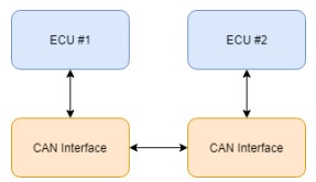
these systems require the ability to communicate with each other, and the CAN communication
protocol was created to solve this problem. This provided a standard method for different
subsystems to send and receive messages between each other via a connection comprised of two
wires.
Although the CAN bus communication was widely adopted after its creation, it carried with it
some small disadvantages that have grown as vehicles and machinery have become more and
more complex. The main problems with the protocol are centered around speed, reliability, and
security.
For some companies in the industry, this has led to the desire for an alternative communication
protocol. The Ethernet standard, being newer, faster and more reliable than CAN, seems, for
many firms, to be the likely upgrade option. For this reason, some companies are considering
upgrading their internal infrastructures from CAN to Ethernet. As with any system upgrade, the
impact of new or different hardware on the system must be considered.
Security is another concern for any communication protocol. If the signals sent between ECUs
are not secure, the intellectual property on the system is at risk of being stolen, copied, or
modified. The solution to this is encryption. Encryption allows the information held within
messages to be systematically scrambled before transmission, and unscrambled once the
messages are received. This ensures that even if messages are intercepted between ECUs, their
contents will be meaningless to whoever has seized them.
Just like with hardware upgrades, changes in system security also bring changes in system
performance. Impacts in system resource utilization and message latency should be examined in
order to fully understand the effects of implementing security measures like encryption.
II. Problem Statement
Komatsu has requested the extension of a project completed last year. That project simulated an
interconnection of ECUs through a CAN bus. The goal of this year’s project is to implement
encryption on the signals sent between ECUs, and to measure the impact that this has on system
utilization and communication latency. Communication over Ethernet with and without
encryption will be implemented and measured as well.
The following are the required functionality that will need to be implemented in order to test
network performance:
- Implement communication between two ECUs over CAN bus.
- Interface with the encryption algorithm to encrypt CAN messages before sending them,
and decrypt the messages after they have been received.
- Implement communication between two ECUs over Ethernet.
- Interface with the encryption algorithm to encrypt Ethernet packets before sending them,
and decrypt the packets after they have been received. - Develop a method of obtaining system performance metrics for both plaintext packets
and messages, and encrypted packets and messages. - Create a method of comparison for all of the cases being tested.
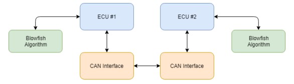
For the ECUs in this project, we will be using two Raspberry Pi 3Bs. As the Raspberry Pi does
not have an integrated CAN bus, each Pi will be fitted with a PiCAN2 shield which will allow
the ECUs to communicate with each other using the CAN protocol. Two 120 ohm terminating
resistors will be require in order for the CAN shield to work properly. Both Pis will need
individual power supplies, and for communication over Ethernet, a single Ethernet cable will be
connected between the systems. For the encryption and decryption of signals, we will use the
Blowfish encryption algorithm. A Linux software solution will need to be used for performance
metric gathering.
III. Background
i. CAN Communication
The CAN communication protocol is a bus standard used in vehicles, equipment, and machinery.
Communication is achieved by setting the voltages high and low on a pair of twisted wires
connected to the bus. Two 120 ohm terminating resistors are required in order to return the wire
pair to their nominal differential voltages of 0 V. Because of this interface, the CAN protocol
allows devices to communicate without the use of a host computer. The top speed of the protocol
is 1 Mbit/s over short distances, with speeds of 250 kbits/s and 125 kbits/s for longer distances.
A combination of signals are sent along the wires to make up a full CAN message. The structure
of messages consists of an arbitration or identifier field (11 bits), a remote transmission request
(1 bit), a data length code (4 bits), and a data field (0 to 64 bits). This means that up to 8 bytes of
data can be stored in a single CAN frame.
In addition to this, there are also sections of the message to mark the beginning and end of
frames, and a cyclic redundancy check (CRC) field. The purpose of the CRC field is to represent
errors that could arise during communication. Possible errors associated with CAN include (but
are not limited to) identifier errors, transmission errors, and receiving errors. The microchip
embedded in the PiCAN2 controller follows the ISO 11898-2 CAN lower-layer standard.
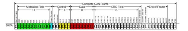
To give a better understanding of how messages are sent over CAN bus, an example of a partial
CAN messages is shown below.
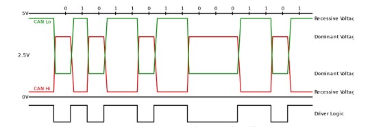
All of the data contained in CAN messages are made up of individual bits, with each bit holding
a value of 0 or 1. These bits are conveyed by the CAN controller through the toggling of voltage
levels on the CAN low and CAN high wires. The dominant voltage levels on the low and high
wires are 1.25 V and 3.75 V respectively. Conversely, the recessive voltage levels on the low and
high wires are 5 V and 0 V respectively. By synchronously setting the low and high wires to
their respective dominant and recessive voltage levels, the CAN protocol has the ability to signal
either a 0 or a 1 for that specified bit.
This system can be seen in the figure above. The green signal represents CAN low, and the red
signal represents CAN high. The black signal labeled “Driver Logic” represents the bit resulting
from the CAN low and CAN high voltage levels. Following this logic, points in the figure where
high and low CAN signals are both dominant result in a logical value of 0 for that bit, while
points in which both signals are recessive result in a logical value of 1.
This process takes place until every bit of the full CAN message is sent.
ii. Ethernet Communication
Ethernet is a computer networking technology often used in local area networks (LAN).
Communication is achieved via twisted wires and in some cases, fiber optics. Commonly, speeds
of 100 Mbits/s can be achieved using this standard, although this varies depending on the size of
the packet (or frame) being sent. Ethernet frames consist of a MAC header, the data, and a
checksum.
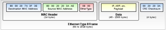
The MAC header is made up of destination and source MAC addresses, and a 16-bit EtherType
identifier. The destination MAC address contains the unique address of the device that the packet
will be delivered to. The source MAC address is the address of the device that is sending the
packet. And the EtherType identifier is used to denote the specific Ethernet protocol being used
to send the packet.
Following the MAC header is the section of the frame that carries the data. This portion has a
size specification of 46 to 1500 bytes. In cases where the data is less than 46 bytes, padding bytes
are appended to the data until the minimum data size is reached.
Finally, a CRC checksum makes up the last 4 bytes of the Ethernet packet. This frame portion,
like in CAN, serves as an error-checking precaution.
iii. Encryption
Encryption is the process of encoding messages into a form, known as a ciphertext, which can
only be decoded by authorized parties. In computing, the encoding process usually consists of
performing a series of XOR and bit-shift operations on the plaintext in combination with a key.
The decoding process performs the reverse of the encoding operations on the ciphertext, using
the same, or in some cases a different, key. Generally there are two types of encryption schemes,
symmetric-key encryption, and public-key (asymmetric-key) encryption.
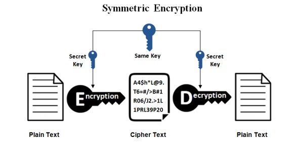
In symmetric-key encryption, the keys used in the encryption and decryption procedures are the
same. This means that the sending and recipient parties must have access to the same key in
order for successful encryption and decryption to be achieved. Without the correct key, the
decrypted text will be meaningless. In symmetric-key encryption, both parties either possess the
key in their program code or in a separate file located on each system, which is then loaded into
the program before encryption or decryption can take place. A visual representation of this
system is shown above.
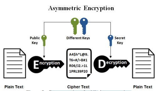
In public-key encryption, keys used for encryption are published or accessible for any party to
encrypt a plaintext string. However, only authorized parties possess the separate key (or keys)
required to decrypt the ciphertext. A visual representation of this system is shown below.
Both encryption schemes have their own advantages and disadvantages, and their applications
depend on the situation in which they are being used.
IV. Implementation
i. Hardware
a. Raspberry Pi 3B
The Raspberry Pi 3B is a small form factor single-board computer designed by the Raspberry Pi
Foundation. The Pi utilizes an Advanced RISC Machine (ARM) architecture which is ideal for
smaller 32-bit and 64-bit machines.

Significant hardware components utilized in this project include the following:
- Quad Core 1.2GHz Broadcom BCM2837 64bit CPU: The central processing unit
(CPU) is arguably the most important component of the system. It is responsible for
executing all program code including the operating system and external programs. All
logic, arithmetic, and input/output (I/O) operations are performed by the CPU. Within the
scope of this project, the CPU ran each of the programs we wrote for communication
between the two systems. Because the process of encryption is essentially a series of
cascaded logic operations, the CPU handled this procedure. As the amount of concurrent
operations performed by the CPU increases, the load on the CPU also increases. By
analyzing the amount of stress a program places on the CPU, it is possible to see how
much of an impact a program’s logic has on the system. We specifically isolated the CPU
load for the programs that were run on ECU #1 in order to compare the difference in load
values for programs sending plaintext messages and programs sending encrypted
messages.
- 1 gigabyte RAM: Random access memory (RAM) is the component of the system that
stores all of the machine code and data being used by the system at a given time. RAM
differs from other storage mediums like hard drives and memory cards in that it is very
high speed memory. Similar to the CPU, RAM usage increases when programs require
more temporary data storage. This was another factor that we looked at in our testing, as
it is another measure of the impact that a program has on the system. - BCM43438 wireless LAN on board: Wireless local area network (WLAN) chips allow
systems to interface with routers, and by extension, other devices that are connected to
that same router. This was of particular importance to our data collection process because
it allowed us to connect into the systems with an external laptop. This meant that while
the main communication programs were running on the systems, we were able to run a
separate program to collect CPU and RAM data pertaining to those programs. Aside from
this, having the Pis connected to the internet allowed us to keep the systems up-to-date
with the latest releases of programs and settings. - 100 Mbits/s Ethernet: The Ethernet port on both systems is what allowed us to connect
the two together for User Datagram Protocol (UDP) communication. This port supported
a maximum speed of 100 Mbits/s which was advantageous as it is the speed that Komatsu
had requested us to use in our testing. - 40-pin extended GPIO: General purpose input output (GPIO) allows the system to
interface with external devices, and enabled us to utilize the CAN shield in our tests.
Although the CAN shield was designed to sit on top of all 40 GPIO pins, we only wired
the necessary pins to their respective ports on the shield. By doing this, we had access to
the remaining pins on the system. This allowed us to use the system’s serial capabilities
while also enabling the full functionality of the CAN shield. Serial communication is a
method of data transmission. In this project, we used two serial-to-USB cables in order to
connect the Pis to a laptop. From this point, we were able to run two terminal emulators
on the laptop using PuTTy. Through PuTTy, we had full control over the systems. - MicroSD port: This port enables the user to provide two key elements to the Pi. The first
of these is a bootable operating system, provided it is loaded onto a microSD card. Since
the operating system is the software that all other programs run on, having microSD ports
on the systems was critical. Additionally, any storage space not used by the operating
system’s files can be used as storage for programs and other files. The specific microSD
cards used in our tests were 8 gigabytes in size. This left us with roughly 4 gigabytes of
extra storage, which was more than enough room for us to develop our programs. - Switched Micro-USB power source up to 2.5A: Like all electronic devices, the Pi
needs a source of power in order to function. The Pi is designed to accept power via a
Micro-USB connector. The Raspberry Pi Foundation recommends a power supply of 5 V
at 2.5 A. Power supplied outside of these specifications can lead to unreliable system
performance and may damage the Pi. In our development and testing, the power supplies
we used comply with the recommended values.
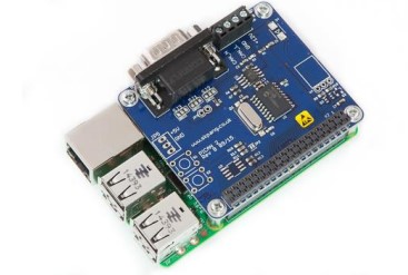
b. PiCAN2
The PiCAN2 shield-board provides the Raspberry Pi with CAN bus capabilities. It sits atop the
Pi so that the system’s GPIO pins connect to the 40 pin ports on the PiCAN2.
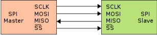
The PiCAN interacts with the Pi through the use of the Raspberry Pi’s Serial Peripheral Interface
(SPI) bus. SPI is a synchronous serial communication interface ideal for short-range
communication. It utilizes master-slave architecture using a single master.
SPI functions using four pins:
- Serial Clock (SCLK): This is the clock signal supplied by the master device, in this case,
the Pi. This sets the pace at which data transmission between the devices will occur. The
SCLK frequency when the PiCAN2 is connected to the Pi is 10 MHz. - Master Output Slave Input (MOSI): Every cycle of the SCLK signal, the master sends
a bit to the slave, and the slave receives it. - Master Input Slave Output (MISO): Every cycle of SCLK, the slave sends a bit to the
master, and the master receives it. - Slave Select (SS): This is the signal used by the master device to select which slave
device to interface with. Master-slave topology allows for multiple slave devices to be
strung together in a daisy chain. However, for each slave associated with a master, the
master must have a corresponding SS pin. It is common for the SS signal to be activelow, meaning that when a low voltage is present, the slave is selected. In this case, the
PiCAN2 is the only slave, so only a single pin is needed.
In addition to these four pins, the shield also requires a 5 V pin, 3.3 V pin, and a ground pin to
power the CAN controller (MCP2515) and CAN transceiver (MCP2551) chips. Both of these
chips enable the shield, and by extension the Pi, to send, receive, and interpret CAN signals.
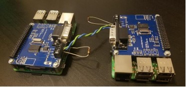
A PiCAN2 was connected to both ECUs, along with a twisted wire pair to connect the CAN high
and low terminals of each shield to each other. 120 Ohm resistors were positioned at the shield
terminals. We initially installed the shield in the standard manner, atop each Pi, but later chose to
wire the shields externally using jumpers.
c. Ethernet Cable
In our testing, an Ethernet cable was required for analysis of UDP communication.
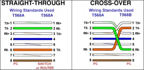
Typically, when directly connecting together two devices of the same family, an Ethernet
crossover cable is the desired medium of linkage. As can be seen in the above figure, a crossover
cable is essentially a standard Ethernet cable with the wires rearranged to provide direct linking
of the respective pins on each Ethernet port. This is in contrast to a standard cable, which is
intended for the connection of a device to a router, switch, or another intermediary system.
Fortunately, the use of a crossover cable was not necessary for this project. The reason for this is
that the pins on the Raspberry Pi’s Ethernet port automatically reconfigure themselves to create
the same effect as a crossover cable when needed.
ii. Software
a. Raspbian Linux
In this project, both Raspberry Pis were running Raspbian Linux. Raspbian Linux is a Debianbased operating system, specifically configured for the Raspberry Pi. The latest Raspbian image
was flashed onto the microSD cards used in the systems. For some of the early development, we
used the operating system’s graphical desktop environment, PIXEL. The advantage of the
interface was that it allowed for convenient file navigation and editing. However, this came at
the cost of increased system utilization because the Pi require the allocation of more resources in
order to display the graphics. For the later portions of the project, specifically the testing phase,
we opted out of using the graphical interface, and strictly used the terminal. This was to ensure
that no extra system resources were being needlessly allocated towards graphics.
b. PuTTY, WinSCP, and SSH server
As previously explained, we interfaced with the Pis through serial and Secure Shell (SSH)
connections. We achieved this through the use of a program called PuTTY. PuTTY is an opensource terminal emulator, serial console, and network file transfer application. Our programs
used for testing were run using the serial console, and additional programs used to monitor
resource usage were run using an SSH connection.
WinSCP, a Windows application, was used to transfer files between the Raspberry Pis and the
development computers. The program uses the Secure Copy Protocol (SCP) to facilitate the
transfer of files over SSH. It allowed for the concurrent editing of files on both Raspberry Pis
using a single Windows computer. This was very convenient because the alternative was to edit
program code using the console interface on the Pis. For small changes to the programs, local
editing of program files was performed using the Linux Nano application. However, when
dealing with files that were hundreds of lines in length, navigating and editing code in Windows
was the practical choice. WinSCP also allowed easy access to the data that was generated from
the programs. We were able to quickly transfer the .csv files to Excel for further analysis.
c. The Blowfish Encryption Algorithm
Blowfish is an encryption algorithm that uses a symmetric-key block cipher system to encrypt
data. It was designed in 1993 by Bruce Schneier, and is open-source. The algorithm supports
key-sizes ranging from 32 bits up to 448 bits, with blocks 64 bits in size. Like other encryption
protocols, Blowfish uses a complex series of digital logic operations to obfuscate data.
Specifically, a Feistel network structure is employed, meaning that relative to algorithms using
different structures, the code for Blowfish encryption and decryption logic is small.
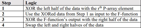
Before encryption can occur, the algorithm requires the data to be split into left and right halves.
In addition to this, two large arrays (P and S) are used in the encryption process and must be
defined ahead of time. At certain points, a function is used to split a 32-bit input into four 8-bit
chunks. This function is known as the F-function. The entire encryption process consists of 16
rounds (r ∈ 1-16), with four steps per round.
The steps are as follows:
d. Programming in C
All the programs designed in this project were written in C, specifically GNU C. This choice was
made because in an actual ECU on a vehicle, Embedded C would be the language used. GNU C
differs greatly from Embedded C in many ways, but of the language options at our disposal, we
chose the language that was most similar to Embedded C. Programming in C also allowed us to
have low-level access to the hardware and socket configurations used for the CAN and Ethernet
tests.
Another advantage of using C was that the Blowfish encryption algorithm was also written in C.
While there do exist ports of the algorithm for languages like Python, there was much more
documentation for the C implementation than for other languages. Also, Komatsu provided us a
very useful program that generated the arrays needed for the Blowfish algorithm to function.
These were the P and S arrays used throughout the XOR and bit shifting operations of the
encryption process. The arrays are constructed using their own algorithm which relies on the
encryption key. Komatsu’s program made this process simple and straightforward.
Finally, the libraries used for CAN and Ethernet communication were also written in C. Linux
provides an open-source, socket-based C library known as SocketCAN, which was authored by
Volkswagen Research. Among other things, the library provides a plethora of convenient
features including CAN-related structures and data frame parsing functions.
Linux also natively packages the C libraries for TCP and UDP communication. For test
programs using Ethernet, we utilized these libraries for the configuration of sockets and the
handling of UDP communication.
More information regarding all code discussed in this section can be found in Appendix B.
V. Testing and Results
Our testing method consisted of two parts. The first was implementing and testing
communication over CAN, and the second was testing communication over Ethernet. In order to
accurately gauge the performance impact of encryption, we needed to test and measure system
performance without encryption. For all cases tested, we chose to analyze round trips for
messages. The reason for this was that we believed this method would round out the data
gathered in the testing process, and would give a better view of overall performance.
i. CAN Testing and Results
In our testing, we chose to first implement and examine CAN communication. This was because
Komatsu asked us to prioritize CAN over Ethernet. The results of the plaintext and encrypted
implementations will be given in parts a and b of this subsection, and a discussion and
comparison of the results will be given in part c.
a. Plaintext Communication
We first wrote programs to send and receive messages in plaintext.
Each ECU was equipped with a separate program to handle the sending and receiving of
messages. A very basic outline of the process is as follows:
- ECU #1 sends a message to ECU #2.
- ECU #2 receives the message, constructs a new message using the same data.
- ECU #1 receives the new message and ensures that it is correct.
To show a more in-depth outline of the logic behind each ECU’s program, see the figure below.
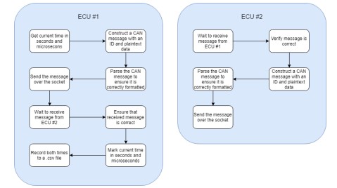
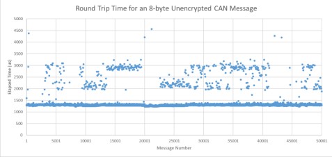
Since we were interested in the time it took for messages to make the complete round trip, ECU
1 took note of two specific times in the communication process. By recording the times at
which the message sending process begins and ends, the total elapsed round trip time for each
message could be found. This data was recorded in an external .csv file for analysis in Matlab
and Microsoft Excel.
Since we were also interested in the CPU and memory usage of the systems, a method was put in
place to gather this data throughout the testing process. Data of this nature was collected using
the Linux command line program, top. Top is a utility that allows users to monitor system
resource usage statistics. It also allows statistics to be isolated to a specific process, which was
very useful in our case.
Initially, we attempted to call top from within ECU #1’s program using C’s system call
functionality. However, we found that elapsed message times were greatly impacted when we
used this method. This was because every time top was called, the program would hang for an
inconsistent amount of time, causing the data to be unreliable. Following this, we opted to
implement an external approach. We found that by connecting to the system through SSH, top
could be called from a separate terminal on ECU #1. Having the programs and top running in
parallel produced much better results. The CPU usage, CPU time, and memory usage for ECU
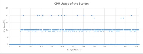
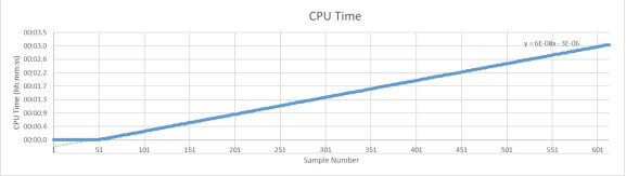
1’s program were all saved to an external .txt file for further analysis in Excel. A series of
50,000 8-byte CAN messages were sent in this test, and the collected data is shown below.
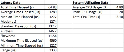
Unfortunately, during the data collection process, we found that the system memory usage did
not vary enough to be of any use in the analysis.
b. Encrypted Communication
A similar process was performed for the analysis of CAN communication with encryption.
The programs used in this procedure were similar to those written for the plaintext tests, except
that the Blowfish encryption algorithm was used for the encryption and decryption of the data
carried within the CAN messages. All of the frames contained data that was 8-bytes in both
plaintext and encrypted form. The communication process consisted of the following high-level
steps:
- ECU #1 sends an encrypted message to ECU #2.
- ECU #2 receives the message, decrypts it, and constructs a new encrypted message using
the decrypted data. - ECU #1 receives the new encrypted message, decrypts it, and ensures that it is correct.
A lower-level representation of the program logic for both ECUs is shown below:
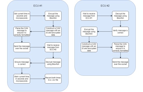
Again, latency was of concern in this test, so the elapsed time for the entire process to take place
was gathered. Times were recorded just before the ECU #1’s encryption of the first message, and
just after ECU #1’s decryption and verification of the second message, sent by ECU #2. This
gave a full view of the total time for the entire process to transpire. These times were recorded in
an external .csv file.
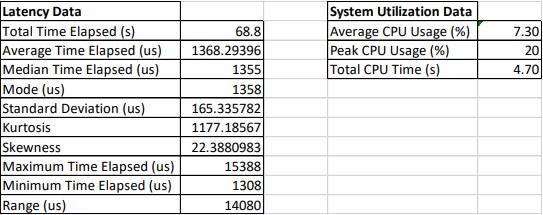
System utilization data was recorded in a manner identical to that in part a, with an external SSH
connection calling top with the individual program ID. The data was recorded to an external .txt
file. Using Excel’s column data importer, the CPU usage and CPU time were extracted from this
file. A series of 50,000 8-byte encrypted CAN messages were sent in this test, and the collected
data is shown below.
Source: Komatsu Sponsored – Performance of an ECU CAN Network With and Without On-The-Fly Data Encryption