
Hey Everyone what's up,
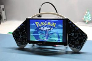
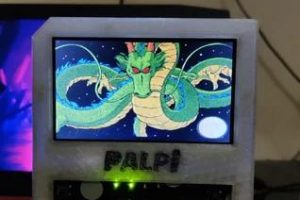
This is the PALPi V2 which is a huge handheld retro gaming console powered by a Rpi 3 B+.
The goal for making this project was to make a low-cost game console like a Nintendo Switch or Steam Deck that can run most retro games that I enjoy.
For Example, Old DOOM, WOLFENSTEIN, Pokemon Games Etc.
This console has more than 40 games preloaded on it. also, we can add any game on this console. for example, I've loaded dragon ball advance adventure on this game console through WINSCP or by manually transferring ROM File on the memory card. (will explain more about this process later in the post)
I first made the PALPi V1 which was powered by a Rpi Zero W, it had a Composite PAL display and it was functional.
To upgrade that setup I prepared the V2 which is now powered by a Raspberry pi 3 B+ and had a 7 inch IPS display that is connected to Rpi with an HDMI Cable.
Previously I made V2 but it was unfinished as it doesn't have custom Buttons and a power distribution board.
To Run PALPi V2, I wired it with my PALPI v1 PCB to just prove the concept that it can work with this setup if we change the shape of the PCB.
It Worked so basically all I had to do was to design two Button boards for the left side and right side buttons pad along with a Power distribution board which also breakout GPIO Pins from RPI headers to separate connectors for connecting the Buttons.
In this Instructables, I'm gonna show you guys how I made this Game console in a few easy steps.
So let's get started!
Supplies
For Power Distribution Board-
- Custom PCBs (that were provided by PCBWAY)
- IP5306 IC
- 10uf 1206 Package Capacitor x8
- 2R 0805 Package x1
- 1K 0603 Package x2
- 10uH Inductor x1
- SMD Button x1
- Indicator LEDs x4
- THT USB Micro Port x1
- 18650 Dual Li-ion Cells holder x1
- Li-ion Cells 3.7V 2600mah x2
- Female Header pins Con40 x1
For Button Board-
- Toggle switch x13
- Custom PCB (Provided by PCBWAY)
For Assembly-
- Raspberry Pi Model 3B+
- 7-inch Display with HDMI Port (got from the PCBWAY Gift shop)
- Power Distribution Board
- Left Side Button Board
- Right Side Button Board
- RED Wires
- Green Wires
- 3D Printed body
- Screws, nuts, and bolts
Step 1: GAMES!
This bad boy can run POKEMON Games, DOOM, WOLFENSTEIN, DRAGON BALL ADVANCE ADVENTURE, and many more.
Step 2: GETTING STARTED- 3D Printed Body
Previously, I prepared the body and basic setup of the PALPi v2 that included the assembly of the whole body and then ran this setup with OLD PALPi V1 PCB.
Step 3: Power Distribution Board- IP5306 Setup
Back then, this setup lacked the power distribution board and left-right side button boards, so I designed them on my OrCad PCB Suite.
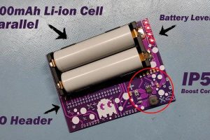
The power distribution board contains an IP5306 IC which is a Li-ion power management IC that is usually used in commercial power banks. It has overcharge and over-discharge protection for Li-ion cells so we dont have to add any external PCM Modules to each cell for protection. It also has fuel gauge indicators that indicate battery level percentage which is just awesome.
Step 4: Powering This Setup
To power this setup, I used 3.7V 2600mAh Li-ion Cells (two of them in parallel).
For adding them directly on the Power Distribution board, I used the 18650 Dual Cell holder which is an SMD component that can be soldered on the PCB's top side.
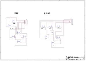
Step 5: Schematic for Both PCBs, Power Distribution Board and Button PCB
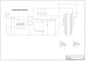
This was the Schematic I used for the Power Distribution board and Button board.
I also added 2 Connector Pins for the Left side buttons and right side buttons on the power distribution board. all the assigned GPIOs are connected to these two Connector Pins.
My plan is to connect the button PCB to this power distribution board manually with wires.
Step 6: Getting PCB Made From PCBWay
After finalizing the PCB, I exported its Gerber data ad send that to PCBWay for samples.
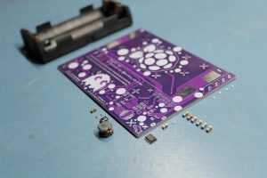
I choose Black soldermask for the buttons board and purple soldermask for the power distribution board.
Now if you look closely, I've added a few graphics on the PCB to increase the aesthetics of the board.
The quality of the PCB I received was just awesome!
PCBWAY did an awesome job of making these PCBs with no problem whatsoever.
checkout pcbway for getting great PCB service for less cost.
Step 7: 3D Printed Body
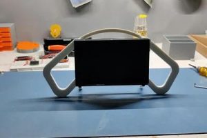
As for the Body of this project, I prepared this body frame which was initially a frame for supporting display.
I made its body in Fusion360 and then 3D Printed all the parts on my ender 3 with white PLA. Then I assembled the whole display and then added Raspberry Pi Model 3B+ on the backside of the display with given mounting holes.
(Cad file is attached)
Step 8: About the Display
As for the Display, I'm using this Raspberry Pi IPS Touch 7-inch Display which I got from the PCBway gift shop.
- Display size: 7 inch
- Resolution: 1024*600px
- Principle: touch controls
- Interface: USB/HDMI/ power interface
- Suitable for: Raspberry Pi/NVIDIA /Windows
- Weight: close 265g
- Support: Raspberry Pi, NVIDIA, Ubuntu mirror, computer secondary screen
Its resolution is 1024*600px, it has an HDMI interface which means we can hook it up directly with Raspberry Pi through a micro HDMI cable.
In my previous Version of PALPi, I used a composite PAL Display which was salvaged from an OLD Car Monitor.
It did work but it lacked the frame rate and refresh rate. the IPS Display that I'm using in the current version is a good display that can support stuff up to 60FPS which is high for a raspberry pi but the point here is that the display I'm using is the best display for this type of game project.
Step 9: ASSEMBLY PROCESS
The Assembly process of this PCB includes three major things, which are
- Solder paste Dispensing Process
- Pick & Place Process
- Hotplate Reflow soldering Process
- THT Componenets soldering
Step 10: Solder Paste Dispensing Process
Now the first step is to add solder paste to each components pad one by one.
To Apply solder paste, I'm using a Solderpaste Dispensing Needle with a Wide syringe, and the solder paste I'm using is a regular solder paste consisting of 63% Tin 37% Lead.
Step 11: Pick & Place Process
After applying Solderpaste we move on to the next step which is to add componenets to their assigned location.
I used an ESD Tweezer to place each component in its place.
Step 12: Hotplate Reflow Soldering Process
After the “Pick & Place Process”, I carefully lifted the whole circuit board and place it on my DIY SMT Hotplate.
The hotplate heats the PCB from below up to the solder paste melting temp, as soon as the PCB reaches that temp, solder paste melts and all the components get soldered to their pads.
we lift the PCB and then place it on a cooler surface for a little bit, to cool down the heat of PCB.
Step 13: ADDING THT COMPONENTS
We add the remaining THT components which are Headerpins and a USB Micro Port.
After adding the THT Componenets, our circuit is completed.
Step 14: Adding the Li-ion Cell to the Board
For the Power source, I'm using these two Li-ion cells each of 2600mah Capacity which means we get a total of 5200mAh Capact as both are connected in parallel.
More capacity here means more battery life which means more fun.
We plug both cells on the holder in right polarity and then use a multimeter to measure the output voltage of IP5306 which should be 5V.
After testing the board, we start the assembly of the Button board which is all through-hole assembly.
Step 15: BUTTON BOARD ASSEMBLY
This is the button board that I made for PALPi V2.
I made its PCB in such a way that LEFT and the RIGHT side is isolated electrically with each other. both are joint only by a RIB that holds two as a single piece.
- we cut down this RIB to separate these two PCBs from each other.
- I first gather all the buttons and start the assembly of switches.
- Assembly is easy, we put switches in their assigned through-hole pads in the right alignment and that's pretty much it.
- After that, I solder all their pads and the THT assembly of the Button board is completed.
Step 16: FINAL ASSEMBLY- Error 404
To start the assembly process, I first had to make a Header pin extension as I didnt realize earlier that I placed the GIPO header pin in the wrong position.
That is no problem as this means I have to now change the direction of adding this power direction board to the RPI But here's another issue. The length of the USB port is greater than the header pins and because of this, we cannot add the Power Distribution board to RPI.
Again, not a problem as I made an extension for the header pins which consists of two 40 header pins male and female.
we place two header pins side by side and solder the connectors with each other.
The goal here is to add this female header pin on RPI and this male header pin connector will get connected with the female header pin on the Power distribution board.
By placing this board in between RPI and power distribution board, we elevate this board a little and we now have no issue of placement for the power distribution board and RPI.
Step 17: Adding Button PCB to the Power Distribution Board
The Button boards will be connected to the body of the game controller from the front side, which means I have to wire it to the power distribution board from the backside.
Step 18: Adding Button PCB to the Body
Now to permanently place the PCB in its place, I added m3 screws from the topside.
Also, because this setup has electronics at the backside, we cannot just place it normally.
I had to make a makeshift ramp to lift the game console body from both sides and keep the middle part lifted from the ground.
The ramp is made from Four Tape Rolls, two on each side is enough to elevate the Game Controller so its electronics won't touch the ground.
After adding the PCBs in their place with screws, I then added a USB cable to 5V and GND of the power distribution board. this USB will power the display.
I then added a small HDMI cable between Display and RPI.
Step 19: FINISHING TOUCHES- Cable Ties
To complete this project, I first added a few cable ties on the left and right side button controller wires.
Step 20: FINISHING TOUCHES- Circuit Supporting RAMP
Now if you look closely, this power distribution board rests its weight entirely on GPIO Header pins, there isn't any supporting structure connected to it.
This circuit has two lithium cells at one side and as a result, it keeps bending downwards.
To eliminate this issue, I 3D Printed this support part that we can glue between the circuit and lower body to make a ramp kinda thing that will support the circuit. I use super glue to attach the ramp to the body of the game console and then used hot glue to connect the circuit with it.
Step 21: FINISHING TOUCHES- Hotglue
At last, I added hot glue onto places where I've done soldering.
And the PALPi V2 is now completed! now we can turn it on and boot it up for the first time!
Step 22: RECALBOX OS
As for the Game Console OS, I am using RecalBox OS here.
Why Recalbox OS, why not Retro Pi or other OS?
well, the answer here is simple, recalbox is an easy-to-use OS that comes with a lot of Free games pre-installed.
Also, it's small and can run on low spec raspberry pi systems.
like in my case, I'm using a Rpi Model 3B+ which has 1GB ram. it's not exactly a powerhouse but it can handle a few retro games without breaking a sweat.
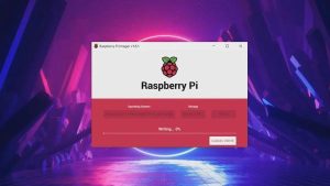
Installing it is also very easy
- Download the Raspberry Pi imager.
- Select the right OS for your device, which would be RecalBox
- select your system which is Rpi Model 3BRaspberry pi imager will do your work of downloading and installing the RecalBox on the memory card.
After installing the RecalBox os, you need to plug your Raspberry pi setup with a Keyboard as the first boot always requires a keyboard.
After booting the whole setup, our RecalBox works like a normal emulator.
Step 23: BOOTUP
To start the setup, we press the button present on the power distribution board and it will turn on the IP5306 IC which will then power Raspberry pi and Display.
we press the buttons and shuffle the stuff inside it. D-pad is for navigating the menu and XYAB is for choosing stuff.
Step 24: Adding BT Speaker for Sound
Now, there's no sound on this setup. but worry not.
This is a Raspberry Pi 3B+ which means it does have Bluetooth which means we can pair any bt device like Bluetooth headphones or a bt speaker with this setup and it will revert the system audio onto it.
- To do that, we go to Setting menu > Bt controller and add a new Bt device.
- pair it up and the Bt system will get active.As for the sound, I'm using my previously made Jack O lantern Bt speaker that you can check out from here.
Now, let's run some games on this setup!
Step 25: Running Games
Recalbox has soo many inbuilt games on it, it even has doom.
We can also play old Wolfenstein on this cool console.
Step 26: Adding Games on It
this is an Opensource retro game emulator, which means we can add any old game from any game system and run them on this setup!
we first need to download the custom ROM of any game you want to play on this game console.
For example, I downloaded pokemon emerald. then we first need to connect the Recalbox to our WIFI router.
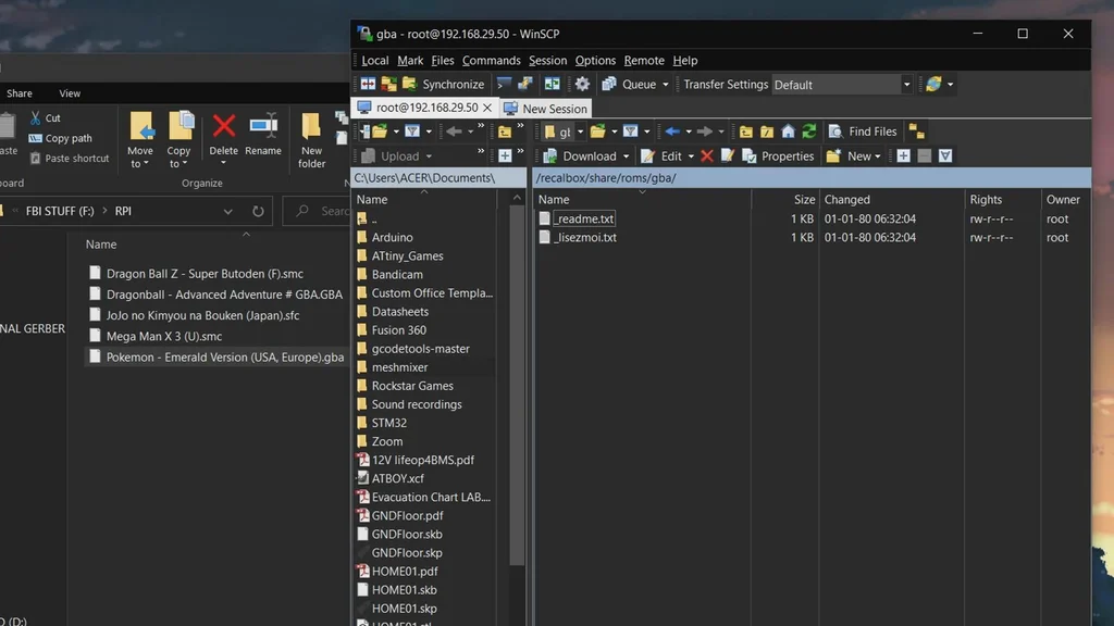
- We open WinSCP and add our Recalbox IP Address on it along with the user name- root, and the password for the pi is recalboxroot.
- go to this menu recalbox>share>rom, it contains all the emulator's folder which contains games ROM, I wanted to add pokemon Emeral in it which runs on Gameboy advance so I had to copy-paste its ROM file in the GBA folder.
- now reboot your raspberry pi setup and open the GBA Emulator menu, and you will see the newly added game.
Step 27: Pros and Cons
Pros of this system are these-
- It's a Low costing Game console that is surprisingly practical as it can run pretty much everything we throw at it.
- The display is larger than the previous edition.
- To increase the power of this setup, we can easily swap the RPI 3B+ with an RPI4 which will increase the system working capabilities and we can run much more powerful games on it through Play station emulator.
- It's completely DIY and easy to remake
Cons of this system are these-
- Making this project requires a lot of time
- It cannot run new games or even mobile games.
- Battery life is a joke, only 3 hours of constant use.
- Because of its size, this setup weighs around 600 grams which is heavy for a game console.
- I'm using a mini HDMI Cable which looks odd from the front side, one way of removing this huge cable is to make a Custom HDMI Cable consisting of two male HDMI connectors connected with a FLEXPCB.
Source: PALPi Version 2, Final Edition