In this tutorial I go through the steps of setting up a Raspberry Pi ADC (Analog to digital converter). As you may already know the Pi doesn’t have any GPIO pins that are analog. This makes connecting analog sensors a little more complex.
There are several solutions to the lack of Analog pins like the one I did in the Raspberry Pi LDR tutorial which involved using a capacitor to measure the resistance of the LDR (Light Dependent Resistor). A better solution to this would be to use what is known as an analog digital converter (MCP3008). This involves a little bit of setting up which I will go into below.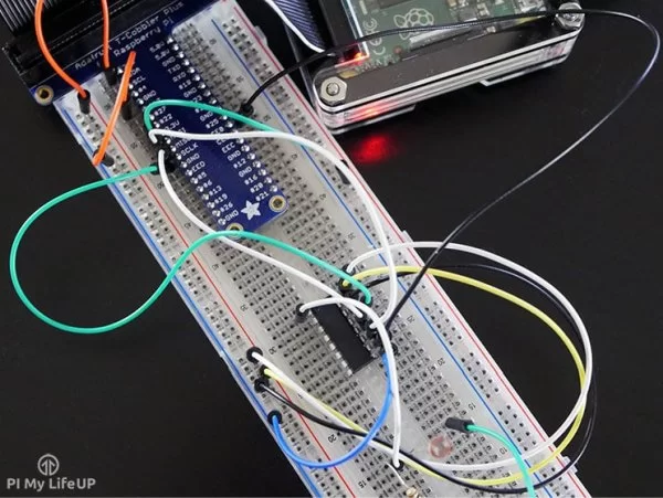
I also go into setting up the MCP3008 with MyDevices Cayenne, this is a much easier process then writing the code from scratch but sometimes half the fun is in learning how to code.
Equipment
You will need the following equipment for this Raspberry PI ADB tutorial. You can use different versions of the analog to digital convert such as an MCP3004 but steps to getting it working may differ from this tutorial.
Recommended:
Micro SD Card or 8 GB SD Card if you’re using an old Rasberry Pi (V1 etc.)
Ethernet Cord or Wifi dongle (Raspberry Pi 3 has inbuilt WiFi)
MCP3008 or similar
Optional:
The Raspberry Pi ADC Circuit
The circuit for connecting the MCP3008 to the Pi looks quite involved but it’s all about just connecting the wires up correctly.
The MCP3008 is the chip that I will be using in this Raspberry Pi ADC tutorial. There is a lot of technical information on this chip but I will just touch on the bare basics.
For anyone who is new to microchips you will find that one end of the chip will have a notch in it. This represents the end where pin 1 is. It is usually the first pin on the left hand side with the notch facing away from you (see diagram below). Pin one also sometimes has a little dot above it.
This particular chip makes use of the SPI (Serial Peripheral interface bus) which means it will only require 4 pins and is relatively easy to communicate to thanks to the SPIDev library for python.
The CH0->CH7 pins (Pins 1-8) are the analog inputs for the MCP3008. On the other side we have a whole range of different pins.
- DGND (Pin 9) is the digital ground pin for the chip.
- CS (Pin 10) is the chip select.
- DIN (Pin 11) is the data in from the Raspberry Pi itself.
- DOUT (pin 12) is the data out pin.
- CLK (Pin 13) is the clock pin.
- AGND (Pin 14) is the analog ground and obviously connects to ground.
- VREF (Pin 15) is the analog reference voltage. You can change this if you want to change the scale. You probably want to keep it the same so keep this as 3v3.
- VDD (Pin 16) is the positive power pin for the chip.
If you want more information on the chip, then you can find the full datasheet over at Adafruit.
Putting the circuit together is pretty straight forward. It is likely to look a bit messy because we’re going to have so many wires but you can clean this up later if you want make it more of a permanent project. In this example I have included an LDR to show how you can get the value on the Pi using the analog to digital converter (ADC).
First connect a 3v3 pin to the positive rail on the breadboard and a ground pin to the ground rail on the breadboard. Also place the MCP3008 chip into the middle of the breadboard.
- VDD (Pin 16) wire this to 3.3V
- VREF (Pin 15) wire this to 3.3V
- AGND (Pin 14) wire this to ground
- CLK (Pin 13) wire this to GPIO11 (Pin 23/SCLK)
- DOUT (Pin 12) wire this to GPIO9 (Pin 21/MISO)
- DIN (Pin 11) wire this to GPIO10 (Pin 19/MOSI)
- CS (Pin 10) wire this to GPIO8 (Pin 24/CE0)
- DGND (Pin 9) wire this to GROUND
Now once you have done that you will probably want to connect the LDR up to the MCP3008 this is pretty easy to do.
First place the LDR onto the breadboard. Next have the 10k resistor go to one end of the LDR and the other end to the positive rail. Have a wire go from in between the LDR and the positive wire to pin 1 (CH0) of the MCP3008. Lastly have a wire go from the other side of the LDR to the ground rail on the breadboard.
If you need further help on making the circuit you can find a detailed diagram below. If you’re still having trouble double check out connections whilst also making sure all the pins are connected correctly.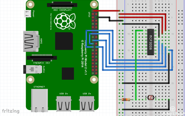
For more detail: Raspberry Pi ADC: MCP3008 Analog to Digital Converter