
Nowadays, home security systems have become a necessity for modern houses. By leveraging the capabilities of the Raspberry Pi and harnessing the potential of the Internet of Things (IoT), it is possible to create a simple and effective home security solution. This project utilizes a Raspberry Pi 3, a webcam, and a PIR motion sensor to design a readily deployable device.
The Raspberry Pi 3 Model B is equipped with built-in Bluetooth (BLE) and Wi-Fi (BCM43438 Wireless LAN) capabilities, making it easy to connect to a Wi-Fi router and access cloud services. The designed device can be installed at the main entrance of a house. It detects motion using the PIR sensor and captures images using a USB webcam. These images are temporarily stored on the Raspberry Pi and then pushed to the Google Cloud. From there, they are sent as email alerts to the homeowner. This allows the user to receive immediate image notifications on their smartphone.
The Raspberry Pi establishes a connection with the Google Cloud using the TCP/IP stack. As the Raspberry Pi 3 has an onboard TCP/IP stack, it can seamlessly connect to an IoT network. OpenCV library is utilized on the Pi to capture images from the webcam and send them to the user's registered email address.
Despite its simplicity, this home security system is a powerful application. By installing this compact device at the main entrance, users can monitor their house remotely at any time and from anywhere. Additional devices can be installed to further enhance security. When an intruder is detected, the user is promptly alerted via email on their smartphone, allowing them to take appropriate action such as contacting the police or informing law enforcement authorities.

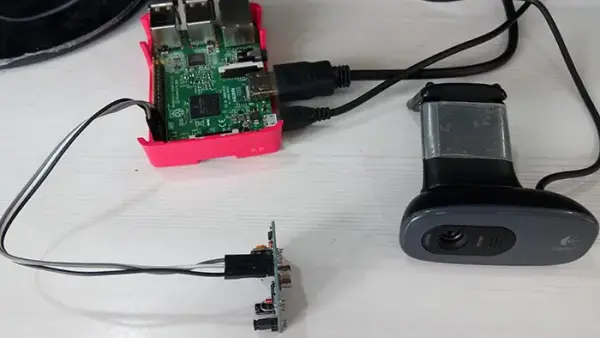
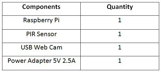
The IoT device developed in this project utilizes the Raspberry Pi 3, which is a compact computer featuring built-in Bluetooth and wireless LAN connectivity. The system incorporates the Raspberry Pi, a PIR sensor, a USB webcam, and a power supply. It can be conveniently installed in any desired location. The PIR sensor is connected to the GPIO pins of the Raspberry Pi for motion detection. Additionally, an LCD monitor can be employed to configure the Raspberry Web Server. The images captured by the USB webcam are saved on an SD card, accompanied by timestamp and date information.
The IoT device developed in this project incorporates various components connected according to the following circuit connections:
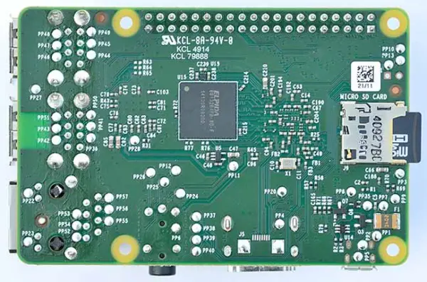
Raspberry Pi 3 – The Raspberry Pi 3 is the third-generation version of the Raspberry Pi. This compact device packs impressive computing power into a credit card-sized form factor. It features a Broadcom BCM2837 system-on-chip (SoC) with a 1.2 GHz Quad-Core ARM Cortex-A53 processor. The SoC integrates the central processing unit (CPU), graphics processing unit (GPU), audio hardware, and communication hardware. Additionally, it includes a 1 GB LPDDR2 memory chip. The BCM2837 employs the ARM instruction set architecture (ISA), distinguishing it from typical desktop or laptop processors.
The Raspberry Pi 3 is equipped with various onboard features, including a 10/100 BaseT Ethernet socket, HDMI and Composite RCA ports for video output, a 3.5 mm audio output jack, a 15-pin MIPI Camera Serial Interface (CSI-2), a Display Serial Interface, Bluetooth 4.1, 802.11 b/g/n wireless LAN, a Micro SDIO slot for a Micro SD card, four USB 2.0 connectors, a 40-pin header containing 27 GPIO pins, and a Micro USB socket for power supply.
The Raspberry Pi is a single-board computer specifically designed to run the GNU/Linux Raspbian operating system, commonly known as Linux. Unlike proprietary operating systems like Windows or OS X, Linux is open source, allowing users to access and modify the source code as desired. In addition to Linux, the Raspberry Pi 3 is capable of running other operating systems such as Windows 10 IoT and various Linux derivatives tailored for embedded systems. The operating system is typically loaded onto a MicroSD card, which serves as the boot device for the Raspberry Pi.
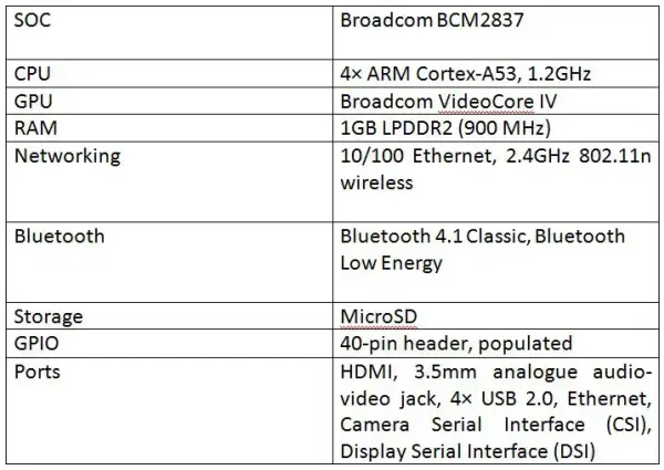
The Raspberry Pi 3 offers powerful computing resources, a wide range of multimedia interfaces, and GPIO pins for connecting external devices. It is an ideal choice for software-driven IoT or embedded projects that require significant computing power and extensive sensor connectivity. With built-in Bluetooth and Wi-Fi capabilities, the Raspberry Pi 3 can easily integrate into an IoT network. The key specifications of the Raspberry Pi 3 are summarized in the table below:
[Please note that without the actual table, I cannot paraphrase the content within it. However, I can help with any specific details or descriptions you may need.]
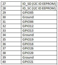

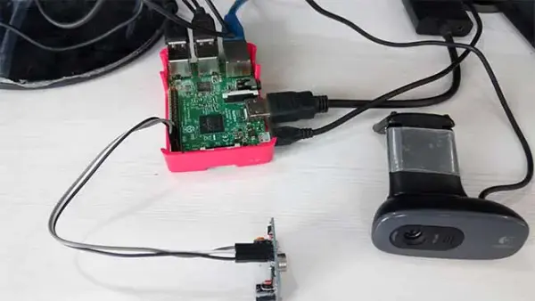
In this project, the USB Web Cam is connected to one of the available USB 2.0 connectors on the Raspberry Pi. Additionally, the PIR (Passive Infra-Red) Sensor is interfaced with GPIO04 (Pin 7) on the header of the Raspberry Pi 3.
The PIR Sensor is a pyroelectric device designed to detect motion by sensing changes in the infrared levels emitted by objects in its surroundings. It utilizes a Fresnel lens and a motion detection circuit to provide high sensitivity and low noise performance. The sensor module is optimized to detect motion up to a range of 6 meters.
The PIR Sensor consists of two slots, each composed of a special infrared-sensitive material. In the absence of any movement, both slots receive an equal amount of infrared radiation. However, when a person passes by the sensor, one of the slots intercepts the infrared radiation, resulting in a positive potential difference across the slots. Conversely, when the person moves away from the sensor, the other slot intercepts the infrared radiation, creating a negative potential difference across the slots. This positive and negative differential generates a pulse, which is utilized to detect motion.
By leveraging the PIR Sensor's motion detection capabilities and integrating it with the Raspberry Pi and USB Web Cam, this project enables the detection and capturing of images when motion is detected, facilitating a home security system.
The sensor module of the PIR Sensor is equipped with several components to enhance its functionality. It includes a built-in 3.3V voltage regulator, a protection diode, sensitivity adjustment, and delay time adjustment features. The module itself consists of three terminals, namely ground, VCC (power supply), and Digital Out.
The VCC pin of the module accepts a voltage range of 5V to 12V, although it is recommended to provide a 5V power supply. When motion is detected by the module, the Digital Out pin generates a HIGH output signal. This signal follows the standard 5V active high logic.
To monitor the signal from the PIR Sensor, the Digital Out pin is directly connected to the GPIO pins of the Raspberry Pi. Specifically, it is connected to the GPIO 4th pin of the Raspberry Pi 3. The VCC pin of the module is connected to one of the 5V DC Power pins on the Raspberry Pi, while the ground pin of the module is connected to one of the ground pins on the Raspberry Pi board.
The USB Web Camera is connected to the Raspberry Pi through one of its USB ports. This allows the Raspberry Pi to interact with and utilize the functionality of the standard web camera module. To facilitate the communication and control of the camera, the OpenCV library is employed.
For the Raspberry Pi to function properly, it requires a suitable power supply. A 5V adapter with a current output of 2A is recommended to power the Raspberry Pi. The power source can be connected to the Raspberry Pi through its Micro USB socket.
How the circuit works –
The IoT device constructed using Raspberry Pi 3 in this project operates in a simple and straightforward manner. It utilizes a PIR sensor to detect motion, and upon detecting motion, it proceeds to capture images. These images are then stored on a MicroSD card and sent to the user's registered email address. The entire system is managed by a Python script running on the Raspbian operating system.
To set up the device, it is necessary to install the Raspbian operating system on the Raspberry Pi 3 and install the required libraries, such as OpenCV, on the operating system. During the installation process, it is recommended to connect the Raspberry Pi to a display monitor using an HDMI cable.
To install the Raspbian operating system on the MicroSD card, you can download the latest Raspbian OS image from the Raspberry Pi website through the provided link.
Raspbian Operating System
To set up the Raspberry Pi with the latest Raspbian OS, follow these steps. Firstly, ensure that you have a MicroSD card with a capacity of 32 GB or below. If so, format the MicroSD card to FAT32 file system. In case the MicroSD card has a capacity of more than 32 GB, format it to exFAT.
Next, download the Raspbian OS image and extract the contents from the downloaded zip file. Connect the MicroSD card to a laptop or PC using a MicroSD card reader and copy the extracted OS image onto the MicroSD card. Finally, insert the MicroSD card into the appropriate MicroSD slot on the Raspberry Pi, following the instructions provided.
The IoT device constructed using Raspberry Pi 3 in this project operates in a straightforward manner. It utilizes a PIR sensor to detect motion, triggering the capturing of images. These images are then stored on a MicroSD card and sent to the user's registered email address. The entire process is managed by a Python script running on the Raspbian Operating System. Before executing the Python script, it is necessary to install the operating system on the Pi 3 and the required libraries, such as OpenCV. To perform the installation, connect the Raspberry Pi to a display monitor using an HDMI cable.
To begin, download the latest Raspbian OS image from the Raspberry Pi website. Ensure that the MicroSD card is formatted to FAT32 if its capacity is 32 GB or below. For MicroSD cards with a capacity exceeding 32 GB, format it to exFAT. Extract the downloaded OS image and copy it to the MicroSD card using a MicroSD card reader connected to a laptop or PC. Once the image is copied, insert the MicroSD card into the designated slot on the Raspberry Pi.
To initiate the Raspberry Pi, connect it to a display monitor using an HDMI cable, and also connect a keyboard and mouse. Power on the board by connecting a power adapter, which will cause the red LED on the board to start blinking, indicating that the OS is booting from the MicroSD card. The boot process will be displayed on the monitor, and once it is complete, the green LED on the Raspberry Pi will light up. After successfully installing Raspbian OS, it is recommended to perform a software update by executing the following Linux commands in the Linux Terminal:
“`
$ sudo apt-get update
$ sudo apt-get upgrade
“`
Next, proceed with installing the OpenCV library. Multiple methods are available for installation, but the simplest approach can be found on the OpenCV website. Follow the provided link for detailed instructions on installing OpenCV on Linux. Open the Linux terminal on Raspbian and execute the following commands:
1. Install the compiler:
“`
$ sudo apt-get install build-essential
“`
2. Install the required packages:
“`
$ sudo apt-get install cmake git libgtk2.0-dev pkg-config libavcodec-dev libavformat-dev libswscale-dev
“`
3. Install optional packages:
“`
$ sudo apt-get install python-dev python-numpy libtbb2 libtbb-dev libjpeg-dev libpng-dev libtiff-dev libjasper-dev libdc1394-22-dev
“`
4. Install OpenCV to a directory:
“`
$ cd <Directory_name>
$ git clone https://github.com/opencv/opencv.git
“`
5. Create a temporary directory for storing generated files:
“`
$ cd opencv
$ mkdir build
$ cd build
$ cmake -D CMAKE_BUILD_TYPE=RELEASE -D CMAKE_INSTALL_PREFIX=/usr/local ..
“`
6. Move to the created directory and install OpenCV:
“`
$ make
$ sudo make install
“`
Once Raspbian and OpenCV are installed, it is time to write and run the Python script on Raspbian. Use a text editor like Leafpad or GNU Nano to write the script, or utilize the default Python IDE such as Python 2 IDLE or Python 3 IDLE. Open Python 3 IDLE by navigating through Menu -> Programming -> Python 3 IDLE. A window named “Python 3.4.2 Shell” will appear. Write the Python script and save it to a specific directory.
To ensure that the Python script runs on startup when the Pi 3 is powered on, several methods can be employed:
1) Editing rc.local:
Edit the file /etc/rc.local
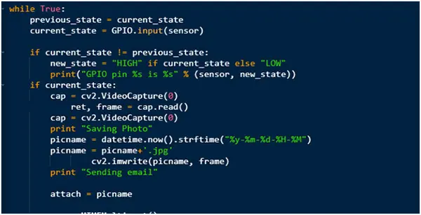
Programming Guide –
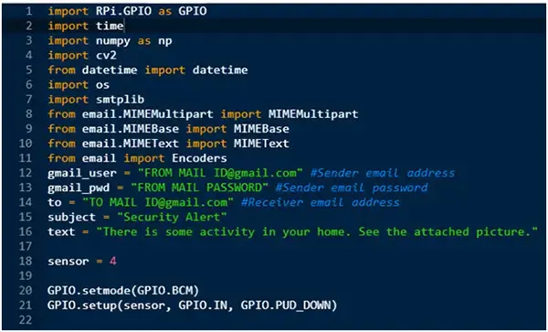
During script execution, it enters an infinite loop where the PIR sensor is constantly monitored for any changes in input. When a change is detected, the camera activates and captures a photo. The captured image is saved with a name based on the date and time, utilizing the datetime module. Subsequently, the image is sent via email, with a specified subject and body content.
Project Source Code
###
//Program to

import RPi.GPIO as GPIO

import time

import numpy as np

import cv2

from datetime import datetime

import os

import smtplib

from email.MIMEMultipart import MIMEMultipart

from email.MIMEBase import MIMEBase

from email.MIMEText import MIMEText

from email import Encoders

gmail_user = "FROM MAIL [email protected]" #Sender email address

gmail_pwd = "FROM MAIL PASSWORD" #Sender email password

to = "TO MAIL [email protected]" #Receiver email address

subject = "Security Alert"

text = "There is some activity in your home. See the attached picture."


sensor = 4


GPIO.setmode(GPIO.BCM)

GPIO.setup(sensor, GPIO.IN, GPIO.PUD_DOWN)


previous_state = False

current_state = False


while True:

    previous_state = current_state

    current_state = GPIO.input(sensor)


    if current_state != previous_state:

        new_state = "HIGH" if current_state else "LOW"

        print("GPIO pin %s is %s" % (sensor, new_state))

if current_state:

cap = cv2.VideoCapture(0)

        ret, frame = cap.read()

cap = cv2.VideoCapture(0)

print "Saving Photo"

picname = datetime.now().strftime("%y-%m-%d-%H-%M")

picname = picname+'.jpg'

                cv2.imwrite(picname, frame)

print "Sending email"


attach = picname


msg = MIMEMultipart()


msg['From'] = gmail_user

msg['To'] = to

msg['Subject'] = subject


msg.attach(MIMEText(text))


part = MIMEBase('application', 'octet-stream')

part.set_payload(open(attach, 'rb').read())

Encoders.encode_base64(part)

part.add_header('Content-Disposition',

    'attachment; filename="%s"' % os.path.basename(attach))

msg.attach(part)


mailServer = smtplib.SMTP("smtp.gmail.com", 587)

mailServer.ehlo()

mailServer.starttls()

mailServer.ehlo()

mailServer.login(gmail_user, gmail_pwd)

mailServer.sendmail(gmail_user, to, msg.as_string())

# Should be mailServer.quit(), but that crashes...

mailServer.close()

print "Email Sent"

os.remove(picname)
###