
Introduction
The Internet of Things ( Smart IoT Devices) is a globally linked network of uniquely addressable items. Many household items, such as televisions, fans, air conditioners, and toys, contain infrared receivers and are operated by an infrared remote. We may wish to link these outdated IR devices to the Internet and control them remotely while keeping costs down. We want to create a low-cost bridge between IR devices and the Internet. In other words, we want to create a smart IR remote with Internet access. To do this, we created a bespoke IR signal recording and the playback circuit board that can be attached to a Raspberry Pi or other low-cost single-board computers. The latest Raspberry Pi Zero W with WiFi functionality, for example, costs under $10. In order to explain how our IR board is utilized, we will use the popular Raspberry Pi as an example in this article. We developed an IR recording tool that can capture IR signals from any IR device's IR remote.
The signal may be replayed and the IR device controlled using our IR replay tool. As a result, the Raspberry Pi may be connected to the Internet, and a smartphone can be used to control the IR device remotely via the Raspberry Pi. The smartphone and Raspberry Pi can be linked to a cloud-based IoT broker, such as Amazon EC2.
Background
- Infrared Communications
Infrared communications begin with the sender rapidly converting pulses into a sequence of 940nm wavelength electromagnetic waves, which the receiver decodes using a technique. The transmitter modulates the pulses at 38 kHz and encodes the signal to decrease noise and jitter, such as that caused by the sun, while boosting transmission accuracy.
Figure 1 represents three well-known signal encoding signals: pulse distance, pulse length, and bi-phase. Encoder refers to the sender, decoder refers to the receiver, “on” refers to the infrared source (e.g., an LED) being turned on, and “off” refers to the infrared source being turned off.
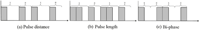
For a 1 and a 0, the pulse distance encoding scheme uses a constant on-length and two distinct off-lengths. It encodes a binary 1 with a on for on-length microseconds, followed by an off for off-length-1 microseconds, and a binary 0 with a on for on-length microseconds, followed by an off for off-length-0 microseconds. It is worth noting that the on time is constant for both binary 1 and 0, however, the off duration affects whether it is regarded as a 1 or 0. Similar to pulse distance, the pulse length encoding scheme uses two different on-lengths for a 1 and a 0 and an off-length; it encodes a binary 1 with a on for on-length-1 microseconds and then an off for off-length microseconds, and a binary 0 with a on for on-length-0 microseconds and then an off for off-length microseconds. The off time for both binary 1 and 0 is constant in this scenario, and the on duration determines whether the signal is identified as a 1 or a 0.
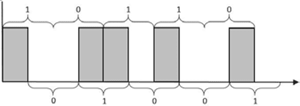
The bi-phase encoding system uses a timeslot, also known as a time window, to encode a binary 1 by a on→off sequence and a binary 0 by an off→on sequence. The timeslot specifies how long each off-and-on will last; it is a constant that must be shared beforehand between the sender and the receiver. Unfortunately, bi-phase encoding can result in incorrect decoding; if the decoder does not identify the start of a bi-phase and misses an odd multiple of timeslots, it can incorrectly recognize a binary 1 as a 0 and vice versa. Figure 2 depicts a bi-phase decoding flip. The sequence 10110 is encoded, but the receiver wrongly decodes it as 01001 because it misses the first on the pulse. As a result, in practice, a known header is used to ensure that the decoder and encoder are in sync, as with the RC5 protocol.
Many manufacturers use a variant of the RC5 or NEC protocols, both of which are modulated at 38 kHz. The RC5 protocol employs bi-phase encoding, with a time slot of 1.78 ms and a 2-bit header “11,” an alternating bit, 5 address bits, and 6 command bits. On relaying inside a button push, for example, if a button is continually pressed, the alternating bit alternates. RC5 is most typically found in audio and video equipment made in the United States and Europe, such as speakers.
The NEC protocol uses the pulse distance encoding scheme with its on-length be- ing 562.5 microseconds, the off-length for 0 being 1687.5 microseconds, and the off-length for 1 being 562.5 microseconds. The NEC protocol starts with a header of 9 ms on and 4.5 ms off. Then, it sends 8 address bits followed by its inverted form and then 8 data bits followed by its inverted form for a total of 32 bits. For example, the full body of a command with an address of 01001000 and data of 00000001 will be 01001000, 10110111 (inverted address), 00000001, and 11111110 (inverted data). The challenge with emulating infrared communications on an operating system like Linux is that the protocols are time sensitive, and utilizing the system clock as a form of time tracking is not always accurate enough. Furthermore, because processes share time with one another, the infrared communication process cannot be executed precisely enough.
- Raspberry Pi and PiGPIO Library
The Raspberry Pi is a small computer powered by an ARM CPU. Although several operating systems are compatible with the Raspberry Pi, all Raspberry Pis in this article utilize Raspbian, a Debian-based Linux OS. The Raspberry Pi 2 and 3 were utilized in this study, but we identify common aspects across other models below to underline that any Raspberry Pi and other comparable devices may be used. The PiGPIO library is a C-based GPIO interface that can perform time-critical GPIO activities by launching a helper daemon. Its main use in this project was to generate time-accurate pulse waves. Due to different delays induced by overhead (e.g., I/O and time-sharing with other processes), using typical file I/O methods to deliver pulses was not accurate enough.
- MQTT
Because of its lightweight and simple nature, Message Queue Telemetry Transport (MQTT) is a popular protocol for implementing IoT connections. MQTT is a publish/subscribe messaging system that is topic-based. A topic is a one-of-a-kind string that acts as the identifier for a certain sort of communication. A publisher is any client that transmits messages that contain both the subject and the payload, whereas a subscriber is any client that waits for messages from a certain topic. Any system that connects to a broker and publishes or subscribes to topics is referred to as a client or node. Mosquitto [5] is an open-source MQTT 3.1 implementation that includes MQTT over TLS. Mosquitto includes a broker executable as well as publishing and subscription capabilities. Paho-mqtt is an MQTT library that offers APIs for subscribing and publishing to an MQTT broker.
IR Transceiver and Smart IR Devices
In this part, we'll go through the hardware and software of our long-range infrared transceiver. We next go through quickly how to use our IR transceiver to transform traditional IR devices into smart devices that can be controlled from anywhere via the Internet. More on Buffers & Transceivers
- Hardware
The schematic of our IR transceiver board is shown in Fig. 3, the PCB design is shown in Fig. 4, and the parts are listed in Table 1. A Raspberry Pi and a transceiver module are standard configurations. The transceiver connects to the Raspberry Pi through four GPIO interfaces. The Raspberry Pi supplies electricity using two GPIO pins, a 5V pin, and a ground pin. The transmitter GPIO pin (J-1) receives signals from the Raspberry Pi to turn on and off the LEDs, with the Raspberry Pi controlling the time. The transceiver's reception pin (J-2) connects to the Raspberry Pi, which captures the signals.
When compared to previous work, the transmitter section of the transceiver features three significant advancements in design [6]. To begin, PNP (Q1) transistors are utilized to pull a 5V power pin rather than pulling straight from the GPIO pin, which only provides 3.3V power. This raises the light's intensity, resulting in a greater range of IR transmission. Second, power is supplied via a 220 uF capacitor (C2) and a 0.1 uF capacitor (C1). Because infrared protocols are fired in short bursts, the 220uF capacitor may hold a charge when the LED is turned off to improve stability in circumstances where the Raspberry Pi fails to deliver a continuous current, and the 0.1 uF capacitor reduces minor electric noise. Finally, four infrared LEDs (D1 D4) are connected in series to optimize coverage. The two outer LEDs are broad and have a short range, but the two interior LEDs are thin and have a great range. The GPIO command is sent through the PNP transistor to each NPN transistor (Q2 Q5), which gets power in parallel from the 5V pin. This system has a range of roughly 10.0 m, whereas a simple GPIO-resistor-LED solution has a range of approximately 2.0 m.
Table 1. Parts list
|
ID on PCB Design |
Part Name |
|
C1 |
Ceramic 0.1uF capacitor (COM-08375) |
|
C2 |
220uF Capacitor with 5V + rating |
|
D1, D3 |
Wide IR LED (IR333C/H0/L10) |
|
D2, D4 |
Narrow IR LED (IR333-A) |
|
Q1 |
PNP Transistor (PN2907) |
|
Q2, Q3, Q4, Q5 |
NPN Transistor (PN2222) |
|
TSSP58038 |
38K IR Receiver Module |
|
R1 |
1KΩ 1/4 W 5% Resistor |
The receiver solution integrates a 38 kHz module with a peak wavelength of 940 nm that can automatically filter out infrared light that is not modulated at 38 kHz. This choice is selected for greater stability and distance when compared to a generic light sensor, and it is validated by the fact that most consumer IR protocols employ 38kHz modulation.
- Software
Separate software is built to connect with the transmitter and receiver, as well as a lightweight library that abstracts most of the low-level complexities of infrared communication. The receiver software, written in C++, records the durations of the receiver's low and high inputs and saves them in a raw format consisting of positive numbers representing the duration in microseconds to turn on the LED and negative numbers representing the duration in microseconds to turn off the LED. A name can be assigned to a recording by the user. By default, the recording is stored to “ircodes.txt,” however this can be overridden in the receiver software's first parameter. The stored recording is a text file with two lines; the first line has “name: name>,” where name> corresponds to the name specified in the receiver's prompt. The second line is a space-separated list of numbers. A positive number indicates that the LED is turned on for that many microseconds, whereas a negative integer indicates that the LED is turned off for that many microseconds. Additional recordings can be combined into a single file.
The PiGPIO library is used by the sender software for nanosecond accuracy in GPIO control, which is required to appropriately replay signals. The software accepts the command's name as the first parameter, compares it to the line reading “name: name>,” and, as previously mentioned, replays the list of numbers appropriately. By default, the sender software attempts to read from “ircodes.txt,” but the file name can be supplied in the second input.
We've also created a large C++ library that abstracts IR signal transmission utilizing our long-range IR transceiver. The sender library supports the aforementioned raw format scheme, as well as pulse-distance, pulse-length, and bi-phase encodings, as well as the NEC and RC5 protocols.
- Smart IR Devices
We can now link our long-range IR transceiver to a Raspberry Pi and operate an IR device by capturing and replaying its IR signals using the IR transceiver hardware and software. We can connect the Raspberry Pi to the Internet and operate the IR device from anywhere because it has Internet connectivity. We demonstrate how to operate an IR gadget from the Internet. We installed a Mosquitto broker on an Amazon EC2 server so that we could publish messages via the smartphone. When a message is received, a Raspberry Pi may subscribe to the topic and send the appropriate signal to the attached IR device.
Security Implications
This section discusses the threats posed by long-range IR transceivers, which may be used to assault many types of IR-controlled equipment.
- Replay Attack
Because similar devices (from the same companies) do not vary their IR codes on a per-device basis, using a simple replay method like the one described in the preceding sections allows anybody to operate the same devices. TVBGone takes a similar method in that the writers pre-record and playback numerous brands of TV on/off toggle signals. Replaying all of TVBGone's code takes around 2 minutes, which is obviously a very fair time range for attacking any TV [6]. Our long-range infrared transceiver is controlled by a Raspberry Pi and is easily customizable to attack any IR-controllable device.
- Brute-force Attack
The brute-force attack goes through every conceivable bit of a particular protocol. The set of all possible commands for NEC is based on distinct addresses and command bits, each of which is 8 bits long, for a total of 16 bits or 2 bytes. There are 5 address bits and 6 command bits in RC5, totaling 11 bits of entropy. A basic ascending technique was used, in which the address bit and command bit are treated as one integer and increased. The brute-force algorithm for NEC, for example, would start at 0x0000 (address = 0x00 and command = 0x00), then try 0x0001 (address = 0x00 and command = 0x01), and so on until 0xFFFF. Small items and products made in Asia, in general, use the NEC protocol.
A remote-controlled light strip, “BINZET 5M 50 LEDs 3AA Battery Operated Copper Wire String Light LED Fairy Light LED Starry Light Cool White Festival Accent Light with Remote Control,” was attacked using NEC brute-force, with the goal of turning on the light strip. Because the light strip's real command was NEC with address 0x00 and command 0x02, the initial bits for the address and command bits were changed to 0x00 and 0x00, respectively; the light strip was brute-force attacked within milliseconds, as predicted.
The above-mentioned basic incremental technique traverses all potential instructions in one minute and twenty seconds per advertisement. As a result, this method is expected to take up to five hours and forty minutes in the worst-case scenario. However, in a fully optimized scenario, which can be implemented by developing a kernel module that accepts queueing of pulses to send (meaning that subsequent commands are sent without delay), each command takes 67.5 milliseconds to send, and there are 65536 distinct commands; the worst-case scenario can be reduced to just over an hour. Due to a lack of feedback (the automated system cannot determine whether or not the correct code was transmitted), the worst scenario must take precedence over the average case.
An RC5 brute-force attack may be done in the same way; the RC5 protocol, which only contains eleven variable bits and takes 24.9ms to communicate, can be completely brute-forced in 51 seconds. A surprising result was that the LED strip took three command signals inside the address 0x00. The timings at which the wrong commands were received varied and were unexpected; the cause for this unpredictable behavior is unknown, although it might be a hardware fault on the light strip.
- Drone Attack
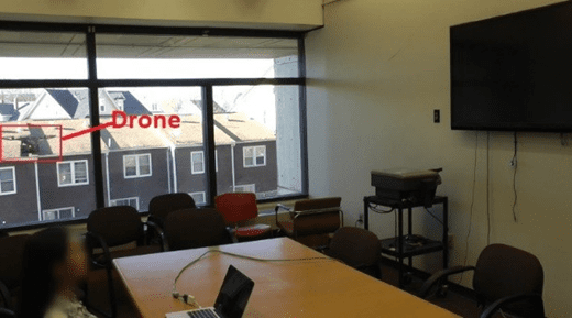
One challenge in attacking infrared devices is that the attacking IR transceiver must be near the target IR devices. We can place the Raspberry Pi and our IR transceiver on a drone to avoid accessibility difficulties. We can control the IR transceiver from anywhere by connecting the Raspberry Pi to the Internet. Figure 5 depicts a drone attack using a DJI Phantom 2. The onboard camera was removed to save weight and thus increase flight length, and a Raspberry Pi 2 with an Anker PowerCore+ Mini 3350mAh battery was installed. The Raspberry Pi 2 is powered by a battery. The drone flew outside a meeting room on the second level. This attack demonstrates how attackers may partially avoid the line of sight restriction; if there is a line of sight from outside through a window, then a drone can be used to give a line of sight for the infrared setup.
Evaluation
This section describes the hardware and software configuration of the device. We assess the total cost of the setup, evaluate our hardware, software, and infrared communication attacks, and then analyze system limits and potential improvements.
- IR Device Setup
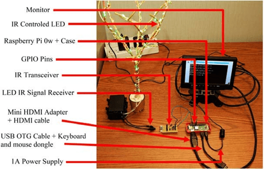
Figure 6 depicts the smart IR device testing setup. An IR-controlled LED (wrapped around a tree-like artifact) and its IR receiver are located on the left side. The IR transceiver circuit board is attached to the Raspberry Pi Zero W through GPIO pins on the right side. The four connected pins on the IR transceiver are linked to the Raspberry Pi Zero W's GPIO 22 (sender pin), GPIO 23 (receiver pin), a 5v power pin, and ground pin, in that order. A USB OTG cable connects the Raspberry Pi Zero W to a monitor, a power source, and a keyboard and mouse dongle.
- Cost
Due to the variability of PCB printing, the total cost of the IR transceiver module is roughly $5.00. (for example building one module is very expensive due to PCB printing). The Raspberry Pi Zero W, which costs about $10.00, was used for this experiment. The software is computationally simple, and more than adequate for a Raspberry Pi Zero W. As a result, using a Raspberry Pi Zero W, the total cost of the complete arrangement may be reduced to around $15.00. More on Analog Switches
- Range of Coverage
The range of the signals is determined by a variety of environmental conditions. The signal's coverage and range are increased by the high reflectivity of walls, limited space, and little external noise (e.g., limiting light from the sun or incandescent light bulbs). To properly characterize IR transmission in rooms, a similar technique to Acoustic Theory may be used. Another important component is the sensitivity and noise tolerance of the device's IR sensor: a higher quality IR sensor (greater sensitivity and better noise filtering) will also enhance the signal's range.
Table 2. Maximum distance for given situations
|
Situation |
Maximum distance (m) |
| Inside, a building corridor |
38.00 |
| Inside, 13×13m room with no pockets |
17.70 |
| Outside, through a window, receiver inside a room |
13.00 |
| Outside, the receiver faces the sun |
1.77 |
| Outside, the receiver facing away from the sun |
4.26 |
| Outside, in the shade |
5.83 |
The maximum range of the IR transceiver module for indoor and outdoor applications is shown in Table 2. The maximum range was calculated by determining the greatest distance between our transceiver and the aforementioned light strip module at which a signal was responsive 10 times out of ten. As predicted, the distance was increased inside, where there is likely to be less noise. Furthermore, windows might reduce range due to their reflectance. As a result, to carry out the drone attack described in Section 4.3, the drone should be at least 13m away from the target device, and in most circumstances, the drone can get extremely near (within 0.5m) to the window, indicating that target devices at most 12.5m away from windows are vulnerable.
All three outside scenarios demonstrate the need for a light bounce for long distances. Furthermore, the experiment revealed that the receiver is more influenced by the sun than the sender; the sender side is not as much affected, as seen by its maximum distance is similar to the Outside, in shadow conditions.
The software was created primarily to increase the usability of the Linux Infrared Remote Control (LIRC) package. Although LIRC is a strong instrument, its usability for basic signal playback is limited, with attempts to learn a signal failing at extremely perceptible rates and taking around thirty seconds. Our software's recording procedure is incredibly speedy and does not fail. Furthermore, the software implements various APIs to abstractify GPIO interaction, simplifying any generic infrared communication needs.
- Security Analysis
Although it is obvious that infrared communication lacks security measures and hence is vulnerable to replay and brute-force attacks, lack of accessibility and effect are key issues that must be solved before targeting infrared.
Lack of accessibility is caused by two factors: distance and obstruction. Infrared light's range is restricted because, as previously stated, there are too many possible sources of interference, causing infrared light to become increasingly unstable as it travels further. Infrared light is blocked by a variety of sources, including walls. A potential workaround involving drones has been offered.
The drone assault revealed that any IR device with a line of sight to target devices, such as via windows, may be abused. Using a comparable attack alleviates some accessibility problems for a determined attacker. A possible difficulty with drone attacks is that the motor noise may draw the target's notice. The endurance of a drone (flight duration per charge) may also have an impact on the effectiveness of the attack. The impact of the incident is currently being discussed. Turning off someone's television is not as serious as stealing someone's credit card information. However, infrared-controlled air conditioners, fans, and thermal control systems, which are popular in Asian nations, are unquestionably dangerous gadgets. Using those devices to arbitrarily modify room temperatures might result in not only health problems but also significant financial loss. Even controlling a television might be dangerous if an attacker turns it on and cranks up the volume late at night.
- Limitations
Because of the nature of the IR spectrum, it acts almost identically to the visible spectrum. To accomplish any IR communication, we must have a direct line of sight between the transceiver and the device. We worked on resolving this issue by increasing both the distance and coverage of the IR module. At lesser distances, a line of sight is not required since the powerful and spread signal will bounce off other surfaces and reach the destination. However, this issue means that multiple configurations may be required depending on the architecture of the house and the location of the old IR devices.
Another issue is the absence of feedback caused by the one-way communication of infrared-controlled equipment. Users, for example, receive feedback from turning on their television by physically seeing the television turn on; they know to click the power button again if the TV does not turn on within a suitable timeframe. However, turning on the TV through the Internet implies that the user will not receive input on the TV's state until the user is already within the appropriate range of the TV, rendering the additional connectivity pointless. To fully treat the legacy device as IoT, additional components such as a camera or microphone must be installed, and those sensor inputs must be trained on a per-device basis. However, because of the high intensity of the emitted lights from the proposed design, interference is rare in an indoor scenario, indicating that an infrared equivalent of packet loss is rarely an issue assuming the transceiver module is not too far away, so users can assume with high confidence that any sent signal will be received.