
Introduction
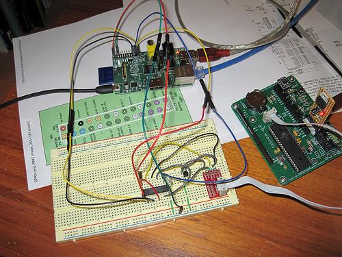
As a fully-featured Linux computer there are many external programmers that can be used with your Raspberry Pi to program the Atmel AVR range of microprocessors. It's also possible to use the general purpose input/output lines (GPIOs) found on the Raspberry Pi to implement an ISP programmer with minimal extra hardware. I say “with minimal extra hardware” because although it can be done with no extra hardware I recommend adding a buffer and FET to protect the Raspberry Pi. You might reasonably wonder what is the point if extra hardware should be used since external USB programmers can be bought cheaply from Ebay. However, if you are going to add an extension PCB to your Raspberry Pi anyway, for instance to communicate with a remote Atmel processor, then including an ISP programmer makes sense and adds very little cost.
AVR ISP programming interface
Most of the Atmel AVR range can be programmed using an ISP interface which resembles the SPI bus. For this description I'll assume that the SPI pins are reused for this purpose but you should check the datasheet to make sure this is true for your part. The RESET pin is used as the active-low chip select pin, SCK is the clock signal, MOSI is the input data pin and MISO is the output data pin. If the directions seem odd remember that the microcontroller is acting as a SPI slave in this scenario; with that in mind the names make perfect sense. The ISP programmer then communicates with the microcontroller, sending commands to read or write flash memory, EEPROM, fuses, and/or locks. Avrdude supports many different programmers which can be used for this task.
Raspberry Pi ISP programmer hardware
The simplest interface on the Raspberry Pi is to use four GPIO pins and bit-bang the SPI commands. I don't recommend this however. After programming has finished the SPI interface on the microcontroller could revert to master mode where SCK and MOSI become outputs. Connecting two logic outputs together which could be at opposite logic levels is not wise.
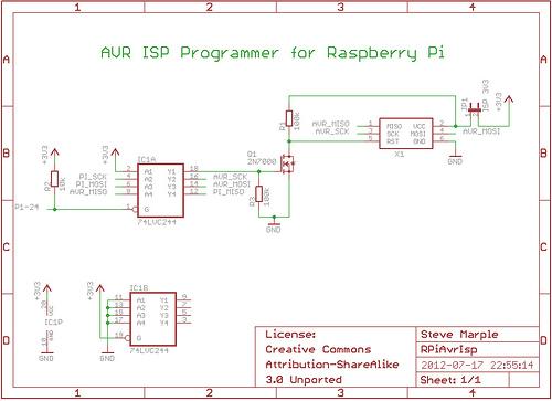 On the target microcontroller the RESET signal is typically connected to a 10 kΩ pull-up resistor, often with a reset switch pulling to ground. The 2N7000 FET provides an open-drain interface which safely connects the Pi to RESET, even if the reset switch is pressed whilst the programmer is connected. Compare this to the case of directly wiring a Raspberry Pi GPIO; pressing the reset switch could short a high-level output directly to ground. Ouch. The 100 kΩ pull-down resistor connected to the gate of the FET ensures it is normally off (and thus RESET is high) when the reset GPIO pin is an input, such as after programming. The 100 kΩ resistor connected to RESET acts as a weak pull-up in case no pull-up resistor is connected to the microcontroller (e.g., for easy programming on a solderless breadboard). In the circuit above a jumper can be fitted to power the target microcontroller from the 3.3 V supply on the Raspberry Pi (care, maximum current 50 mA).
For more detail: AVR/Arduino ISP programmer using the Raspberry Pi GPIOs