
Exploring the GPIO pins on your Raspberry Pi presents numerous exciting opportunities. Acquiring a foundational understanding of these pins through beginner projects allows you to delve into the realms of DIY electronics and programming.

In this tutorial, you will discover two methods for integrating a button into your Raspberry Pi project. The button's purpose will be to control an LED, and detailed written instructions accompany the instructional video provided below.
You Will Need
Before diving into the project, it's important to ensure you have the necessary components at hand:
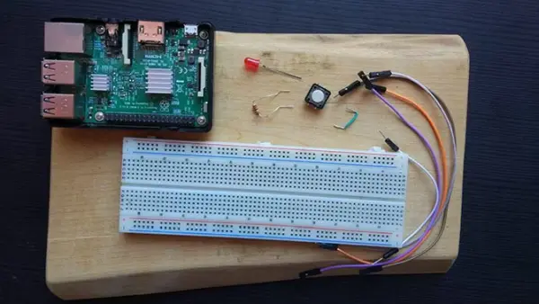
1 x Raspberry Pi (Any model will suffice, although this tutorial employs model 3B) 1 x Push Button 1 x LED 1 x 220 Ohm Resistor (Note that higher resistor values will result in a dimmer LED) 1 x Breadboard Hook-up wires
Once you've gathered these components, your setup should resemble the following image:
Additionally, it's essential to have an SD card with the Raspbian operating system already installed. The easiest method to achieve this is by utilizing the NOOBS (New Out Of the Box Software) image. For detailed instructions on how to accomplish this, refer to the following video:
Setting Up the Circuit
To create the circuit, you will utilize the GPIO pins on the Raspberry Pi. If you're not familiar with the GPIO pins, you can refer to our comprehensive guide on Raspberry Pi GPIO pins for assistance. The circuit for this project is similar to our previous Raspberry Pi LED project, with the inclusion of the button you'll be working with today.
Follow the provided diagram to set up your circuit:
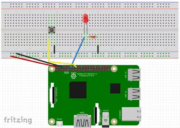
- The 5V and GND pins are connected to the power rails of the breadboard.
- Pin 12 (GPIO 18) is connected to the positive leg of the LED.
- One leg of the resistor is connected to the negative leg of the LED, while the other leg is connected to the ground rail of the breadboard.
- Pin 16 (GPIO 23) is connected to one side of the button, and the other side of the button is connected to the ground rail of the breadboard.
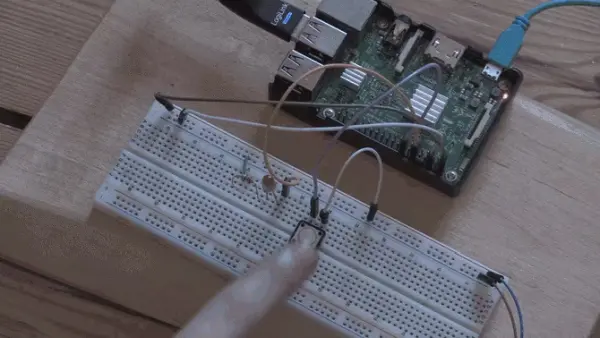
Once the connections are made, your circuit should resemble the following image:
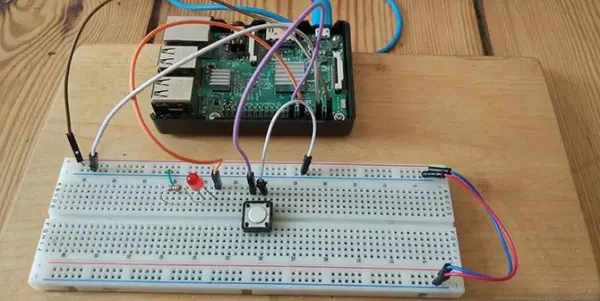
Verify your circuit to ensure its accuracy, and then proceed to power on your Raspberry Pi.
Method 1: The RPi.GPIO Library
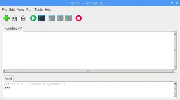
After the Raspberry Pi has finished booting, navigate to the menu and choose “Programming” followed by “Thonny Python IDE.” This will open a new Python script. If you're new to Python, don't worry! It's a beginner-friendly programming language, and there are plenty of resources available to expand your knowledge once you've completed this tutorial.
Begin by importing the RPi.GPIO library and configuring the board mode.
import RPi.GPIO as GPIO
GPIO.setmode(GPIO.BOARD)
Next, define the variables for the LED and button pin numbers.
buttonPin = 16
Setting Up the Button
Now it's time to configure the GPIO pins. Set the LED pin as an output pin, and the button pin as an input pin with a pull-up resistor.
GPIO.setup(ledPin, GPIO.OUT)
GPIO.setup(buttonPin, GPIO.IN, pull_up_down=GPIO.PUD_UP)
The text after GPIO.IN refers to enabling the internal pull-up resistor of the Raspberry Pi. This is necessary to obtain a reliable reading from the button. Since the button is connected to the ground pin, the pull-up resistor ensures that the input pin remains in a HIGH state until the button is pressed.
Before we go on, let's look at pull-up and pull-down resistors.
Intermission: Pull Up/Pull Down Resistors
When you set a GPIO pin to input mode, it reads the state of that pin to determine its condition. In this particular circuit, you need to determine whether the pin is in a HIGH or LOW state in order to activate the LED when the button is pressed. Ideally, it would be straightforward if those were the only two possible states for a pin. However, there is a third state known as FLOATING.
A floating pin refers to a pin that has a value between HIGH and LOW, leading to unpredictable behavior of the input. To address this issue, pull-up and pull-down resistors are employed as a solution.
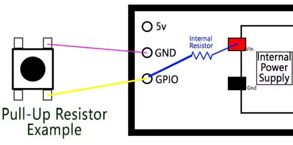
The diagram provided above offers a simplified representation of a button connected to a Raspberry Pi. In this configuration, the GPIO pin is connected to the ground via the button. The internal pull-up resistor links the GPIO pin to the internal power supply of the Pi. As a result, a current flows, causing the pin to be pulled up to a HIGH state.
When the button is pressed, it establishes a direct connection between the GPIO pin and the ground pin, resulting in a low reading from the button.
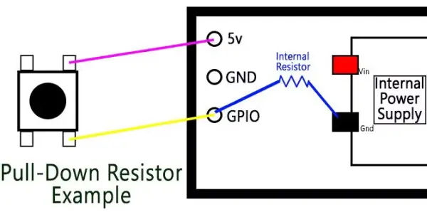
Pull-down resistors, on the other hand, are utilized when the switch is connected to the power pin. In this case, the internal resistor connects the GPIO pin to the ground, maintaining a LOW state until the button is pressed.
Understanding the theory behind pull-up and pull-down resistors may seem confusing initially, but it is a crucial concept to grasp when working with microcontrollers. If you find it challenging to comprehend at this moment, there's no need to worry. We can proceed with the tutorial from where we left off.
The Program Loop
Next, set up the program loop:
while True:
  buttonState = GPIO.input(buttonPin)
  if buttonState == False:
    GPIO.output(ledPin, GPIO.HIGH)
  else:
    GPIO.output(ledPin, GPIO.LOW)
The while True loop continuously executes the code within it until we terminate the program. During each iteration, it updates the buttonState variable by reading the input from the buttonPin. As long as the button is not being pressed, the buttonState remains HIGH.
Once the button is pressed, the buttonState changes to LOW. This triggers the if statement since a False value is equivalent to LOW, causing the LED to turn on. On the other hand, the else statement turns off the LED whenever the buttonPin is not in the False state.
Save and Run Your Script
To save your script, go to the File menu and select Save As. Choose a suitable file name for your script. To run the script, you can click on the green Play button located in the toolbar of the Thonny IDE.

After successfully running the script, you can press the button, and you should see the LED light up. If you want to stop the program at any point, simply click on the red Stop button.
If you're experiencing any difficulties, make sure to carefully review your code and double-check your circuit setup for any errors. It's important to troubleshoot and identify any potential issues before trying again.
Method 2: GPIO Zero Library
The GPIO Zero Library, developed by Raspberry Pi community manager Ben Nuttall, offers an alternative to the RPi.GPIO library. Its purpose is to provide a simpler and more user-friendly coding experience, making it easier to write and understand code for Raspberry Pi projects.
from gpiozero import LED, Button
from signal import pause
Instead of importing the entire library, you only need to import the specific modules that correspond to the LED and button functionalities you'll be using in your script. Additionally, you'll import the Pause function from the signal library, which is used for event management in Python.
Configuring the pins becomes simpler with GPIO Zero, as shown below:
led = LED(18)
button = Button(23)
With the GPIO Zero library, there are specific modules available for the LED and button, eliminating the need to manually set up inputs and outputs as before. It's important to note that the pin numbers used in GPIO Zero are different from the previous example because GPIO Zero uses GPIO pin numbers, also known as Broadcom or BCM numbers.
The remaining script consists of just three lines:
button.when_pressed = led.on
button.when_released = led.off
pause()
In this code snippet, the pause() function is used to prevent the script from exiting immediately. The two button events, button.when_pressed and button.when_released, are triggered when the button is pressed and released, respectively. By saving and running the script, you will observe the same outcome as before.
Two Ways to Add a Button to Raspberry Pi
Among the two methods for setting up the button, the GPIO Zero approach appears to be the simplest. However, it is still valuable to familiarize yourself with the RPi.GPIO library since it is widely used in beginner Raspberry Pi projects. Despite the simplicity of this project, the knowledge gained can be applied to various other endeavors.
Utilizing the GPIO pins offers a fantastic opportunity to learn and innovate, but it represents just a fraction of what you can accomplish with the Pi. Our unofficial Raspberry Pi guide is filled with imaginative ideas and tutorials that you can explore on your own. For another tutorial similar to this, consider checking out our guide on creating a Wi-Fi connected button.