
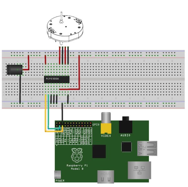
I’ve been intending to try driving Switec X25.168 motors using the MCP23008 I²C I/O port expander chip from an Arduino, but it occurs to me that it might be more interesting to try this on a Rasberry Pi. If it works, it will demonstrate a simple and very inexpensive method for driving analog gauges from the Raspberry Pi without the need for high-current drivers.
The MCP23008 provides 8 I/O lines controlled via an I²C interface.
The datasheet is available here. The pins are rated to source and sink 20mA each. That’s around half what an Arduino offers, but should be (just) enough to drive our little Switec steppers. These chips are available from Adafruit, along with the doubly awesome 16-port MCP23017.
Since this is my first Raspberry Pi project, I’ll include detailed setup notes.

Step 1 – Installing AdaFruit’s Occidentalis Kernel Image
Adafruit have prepared a modified version of the Wheezy Linux distribution for the RPi that includes I²C tools and drivers (plus SPI, one wire, and plenty of other hackable goodness.) The first step is to create a bootable SD card containing Adafruit’s Occidentalis image. The following instructions are for OSX.
Insert a 4GB SD card and figure out it’s device name using diskutil list. It is easy to recognise the SD card in the list below as /dev/disk2 because of the 4GB size.
Next unmount the disk with diskutil unmountDisk.
|
$ diskutil unmountDisk /dev/disk2
Unmount of all volumes on disk2 was successful
|
Download Occidentalis from AdaFruit. I’m using Version 0.2. Unzip it, verify the checksum, and copy it to the SD card. I know this a big file, but I was still surprised it took half an hour to write to the SD card.
Step 2 – Test the Boot Image
Boot the RPi from the newly copied SD image and log in. The default username is ‘pi’, password ‘raspberry’. DHCP and ssh are enabled by default so you can login headless if you can figure out the IP address from the DHCP server.
Confirm that the I²C tools are installed and working by doing an I²C scan of bus 0. You should see nothing on the bus, as shown below.
I wired up a VID29 to pins GP0 to GP3 on the driver chip and kludged together some C code to cycle through the 6 signal states used to drive the motor. I’m using a VID29 motor with the stops removed so I can let it spin continuously without hitting the stop. The test code is here.
Yeah, so those errors aren’t good. The results of reading the 10 registers look fine, but as soon as it starts trying to turn the motor we are getting errors. After some fiddling I confirmed that the errors only happen when the motor is attached, so it looks like the RPi’s 5V power rail isn’t able to supply the necessary current. This is not actually a surprise, and it isn’t a big problem either.
I happen to have a beefy 10A 5V supply on the bench, so used that to power the MCP23008. Problem solved, motor turns, errors are gone.
For more detail: Analog Gauges Using I²C on the Raspberry Pi