
Indeed, we discovered that mobile phone camera modules can be extracted from various mobile phones and incorporated into our advanced hobby electronics projects, similar to other standard add-on modules. To facilitate this integration, it is advisable to employ an appropriate microcontroller. In this regard, using microcontrollers such as Arduino or Raspberry Pi proves to be a beneficial platform. These microcontrollers offer versatility and utility for effectively interfacing with the mobile phone camera modules in our projects.
Raspberry Pi camera
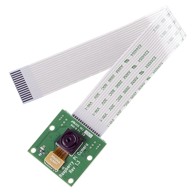
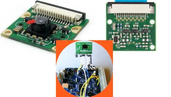
I recently acquired a Raspberry Pi camera board that comes pre-assembled with a ribbon cable. This compact board measures 25mm x 20mm x 9mm and features a fixed focus 5MP camera module. The camera module, with a part number of OV5647, is manufactured by OmniVision. It incorporates a 1/4″ color CMOS QSXGA (5 megapixel) image sensor equipped with OmniBSI™ technology.
The Raspberry Pi camera module offers the capability to capture high-definition videos and still photographs. It is designed to be user-friendly, making it suitable for beginners, while also providing advanced users with ample opportunities to expand their knowledge and explore more advanced functionalities.
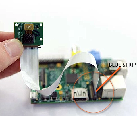
The Raspberry Pi is equipped with two excellent connectors on its board. One connector is positioned between the Ethernet and HDMI ports, while the other is located near the GPIO (General Purpose Input/Output) pins. The connector closest to the Ethernet port is known as the Camera Serial Interface (CSI). This CSI interface establishes a direct connection between the Raspberry Pi's GPU (Graphics Processing Unit) and the camera module. As a result, the GPU is capable of processing images independently, without requiring intervention from the ARM (Advanced RISC Machines) processor.

When connecting the camera module to the CSI port located behind the Ethernet port on the Raspberry Pi board, it is important to ensure that the camera cable is inserted correctly. The flexible cable should have its blue strip oriented towards the Ethernet (LAN) port. Once the connection is established, you can enable the camera software and proceed to test and utilize the camera using either Bash or Python.
As a newcomer to the Raspberry Pi world, I haven't extensively explored all the features and capabilities of my borrowed Raspberry Pi and its camera module. If you are interested in exploring the vast possibilities and diving into the future of amazing projects, I recommend referring to the documentation available at: http://www.raspberrypi.org/help/camera-module-setup/
The Raspberry Pi camera board utilizes a high-speed camera serial interface (CSI-2) bus to transmit data directly to the system-on-chip (SoC) processor. This is achieved through a 15-pin ribbon cable, commonly known as a flexible flat cable (FFC), which connects to the surface mount ZIF 15 socket on the Raspberry Pi board. It is worth noting that the camera module included in this official Raspberry Pi camera board is identical to the camera modules (ccd imagers) found in many mobile phones.
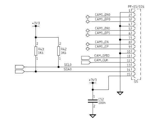
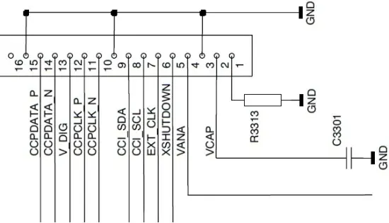
Fortunately, the majority of mobile phone cameras not only comply with the MIPI (Mobile Industry Processor Interface) standard but also adhere to the CSI (Camera Serial Interface) standard, as mentioned in the earlier part of this article. To aid you in your tinkering endeavors, the pinout for the 15-pin Raspberry Pi CSI interface connector is also provided here.
It's important to note that the Raspberry Pi features two flexible flat cable (FFC) connectors, namely S2 and S5. S2, positioned near the micro USB connector, serves as the Display Serial Interface (DSI) connector. It enables low-level interfacing with LCDs and other display devices compatible with Raspberry Pi. This connector is a 15-pin surface-mounted flexible flat connector, providing two data lanes, one clock lane, and connections for 3.3V and GND.
On the other hand, S5, located between the LAN and HDMI connectors, is the MIPI Camera Serial Interface 2 (CSI-2) connector dedicated to camera modules. It is a 15-pin surface-mounted flat flexible connector that provides two data lines, one clock lane, a bidirectional control interface compatible with I2C, and connections for 3.3V and GND. The CSI interface employs a unidirectional differential serial interface for data and clock signals, following the MIPI Alliance Standard for DPHY as its physical layer.
Arduino camera
If you wish to add a camera to your Arduino UNO, you'll be glad to know that the ArduCAM™ Shield is available to assist you. The process is relatively straightforward. A comprehensive tutorial on using the ArduCAM shield with the Arduino UNO board can be found at http://www.arducam.com/tutorial/.
This tutorial will guide you through the steps of utilizing the ArduCAM shield. By following the instructions, you will learn how to aim the camera and capture a snapshot by pressing a dedicated button. The resulting image will be saved as a BMP file on the SD/TF card connected to the shield. It's an excellent resource to help you successfully integrate a camera module with your Arduino UNO.

The ArduCAM shield hardware incorporates all the essential components required to interface with camera modules. Users only need to acquire compatible camera modules and a TF/SD card to commence image capture. The ArduCAM shield includes an ArduChip that efficiently manages the complex timing coordination between the microcontroller unit (MCU), LCD, camera, and FIFO. It provides a standard SPI serial interface, making it compatible with a wide range of microcontrollers.
Moreover, the ArduCAM shield is equipped with two sets of pinouts, both serving the same functions. One set conforms to the Arduino standard, enabling seamless integration with popular Arduino boards such as UNO, MEGA2560, Leonardo, and DUE. The other set comprises an alternative port that can be connected to various platforms, including Raspberry Pi.
Building upon the success of the ArduCAM shield Rev.B, the ArduCAM team has now introduced an even more powerful iteration called ArduCAM shield Rev.C. This revised version offers remarkable new features. It supports an extensive range of camera modules, including OV7660, OV7670, OV7675, OV7725, OV2640, OV3640, OV5642, and MT9D111.
Have you ever come across the fact that the CMOS image sensor interface can be categorized into two classes? One class is the DVP (Digital Video Port) interface, while the other is the MIPI (Mobile Industry Processor Interface). The key distinction between these two interfaces lies in their operation. DVP operates as a parallel interface, whereas MIPI is a high-speed differential serial interface.
It's worth noting that the MIPI interface offers several advantages over the DVP interface. The MIPI interface provides a higher data bandwidth, enabling it to support higher resolutions and frame rates compared to the DVP interface. This makes the MIPI interface an ideal choice for applications that demand enhanced performance and throughput.
Typically, image sensors are relatively inexpensive, and you can find them for as low as $5.00 on platforms like eBay. However, when these image sensors are transformed into “microcontroller-compatible camera modules,” the finished boards tend to be significantly more expensive.
Considering this, I believe that investing time and effort in creating your own camera modules can be worthwhile. The process of reverse engineering and hacking can be incredibly fascinating and rewarding, at least in my opinion. This serves as a starting point for exploration, and I promise to provide valuable updates in the near future. Stay tuned for more!