
Introduction
For this assignment, your objective is to set up and test a development environment for the Raspberry Pi 3, specifically for ARM64 architecture. This environment will be utilized throughout the remainder of the course. You will be installing the necessary tools and creating your first bare-metal application, which is an LED blinky program, using two programming languages: C and Rust.
The assignment is divided into four phases. In the first phase, you will install the essential software that enables communication between your machine and the Raspberry Pi. Additionally, you will verify the proper functioning of your Pi by running a pre-compiled program.
Moving on to the second phase, you will connect an LED to GPIO pin 16 on your Raspberry Pi and execute a second pre-compiled program to ensure that your connections are correctly established.
In the third phase, you will write a C program that toggles GPIO pin 16 on and off, thereby making the LED blink on your Pi. This program will be cross-compiled and linked.
Lastly, in the fourth phase, you will repeat the process by writing the same program in Rust. The Rust program will also be cross-compiled and linked.
By completing these four phases, you will have successfully set up your Raspberry Pi development environment, tested its functionality, and created LED blinky programs in both C and Rust languages.
Phase 0: Preflight Check
First and foremost, please verify that your Raspberry Pi kit contains all of the following components:
1 x Raspberry Pi 3/B/B+
1 x microSD card (with a capacity of 4-32GB)
1 x microSD card reader
During the class, we will provide you with the following items:
1 x CP2102 USB adapter
4 x female-female jumper cables
5 x multicolored LEDs
5 x 100 ohm resistors
10 x female-male DuPont jumper cables
Since electronics are susceptible to electrostatic discharge, it is crucial to ground yourself before handling any electronic components. To do this, simply touch something conductive before touching the electronics. Additionally, prepare two male-to-female jumper cables, one resistor (any value will work), and one LED. Finally, have the USB microSD card adapter readily available for use.
Getting the Skeleton Code
To get the skeleton code for lab1, you should fetch the updates from our git repository to your development machine.
$ git fetch skeleton
$ git merge skeleton/lab1
This is the directory structure of our repository.
.
├── bin : common binaries/utilities
├── doc : reference documents
├── ext : external files (e.g., resources for testing)
└── tut : tutorial/practices
    ├── 0-rustlings
    └── 1-blinky : this contains files for lab1
Since your previous lab changes are located in the tut/0-rustlings directory, it is unlikely that the merging process will be smooth and without conflicts. If conflicts arise, please resolve them accordingly before moving on to the next phase.
Feel free to navigate through the repository and explore its contents.
Phase 1: Baking Pi
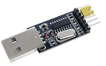
To power and establish communication with your Raspberry Pi, the primary method involves using a CP2102 USB module. This module is recognizable as the red USB dongle with five pins.
If you are working on a virtual machine, it is necessary to configure specific settings to enable the USB port for the microSD card adapter and CP2102. If you haven't set up these configurations yet, please refer to the Tools page for instructions.
To verify the proper functionality of your CP2102, connect it to a USB port on your development machine with the yellow cap attached. The cap serves to connect the TXD and RXD pins of the serial device, effectively linking the input and output pins. Consequently, any data sent will be received as well.
To view the data received from the CP2102 module, you will need to utilize a serial console emulator that connects to the CP2102 module and reads incoming data. In Linux, we will use the “screen” emulator, as it is preinstalled. Remember the “/dev” path assigned to your CP2102 module (typically “/dev/ttyUSB0”), and establish a connection to the CP2102 USB module using screen by running the following command:
$ screen /dev/<your-path> 115200
You may have to use sudo to run the command. Alternatively, you can add yourself to the dialout user group to avoid using sudo:
$ sudo gpasswd --add <your-username> dialout
Assuming everything is functioning correctly, you should observe that the characters you type in the screen console are displayed, and the LED lights on the USB module blink in sync with your keystrokes. Once you have confirmed that the CP2102 is working as intended, it is time to establish the connection between the CP2102 and the Raspberry Pi. To exit the screen console, press followed by “k” and respond with “y” when prompted.
Powering the Pi
To begin, disconnect the CP2102 module from your computer. Next, establish a connection between the Raspberry Pi and the CP2102 module using four female-female jumper cables. The table below indicates the corresponding pins on the CP2102 module and the Raspberry Pi that should be connected. You can find the names of the pins on the CP2102 module by examining the back of its board.
By following this table, connect the respective pins from the CP2102 module to the corresponding pins on the Raspberry Pi.
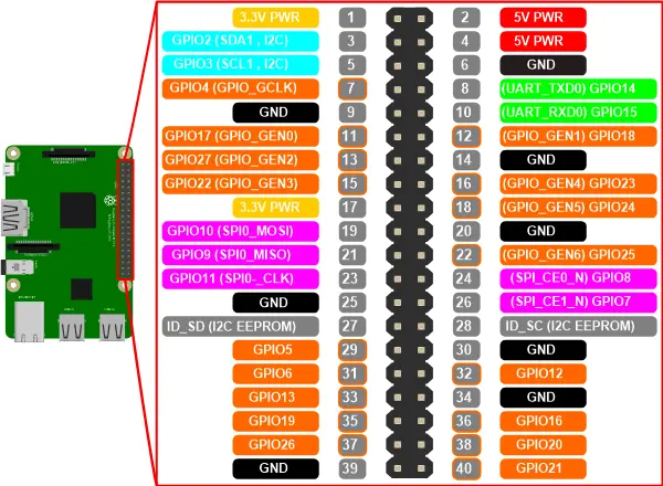
Here’s how the pins are numbered on the Raspberry Pi 3:
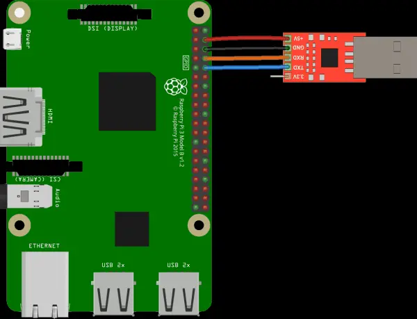
Here’s what the connections should look like (connections not ordered in this pic, just look at the name of the pins):
Before proceeding, it is crucial to double-check, triple-check, and even quadruple-check your connections! It's also a good idea to have a friend verify your connections as well. Incorrect wiring can potentially damage your Raspberry Pi, and while there may not be an automatic failing grade for such an incident, Raspberry Pi 3 boards are expensive, and it's best to avoid any unnecessary damage. So, please quintuple-check your connections to ensure their accuracy before moving forward.
Once you are confident in your connections, it's time to plug in your CP2102 module into your computer. If everything has been properly set up, you should notice a bright red LED light shining on your Raspberry Pi. Congratulations! You have successfully established the power and communication capabilities with your Raspberry Pi.
Please make sure to double-check, triple-check, and even quadruple-check your connections! It's crucial to have someone else verify your connections as well. Incorrect wiring can lead to a damaged Raspberry Pi, which we definitely want to avoid. Although it's not true that it will result in an automatic F in this course, Raspberry Pi 3's are quite expensive, and we'd prefer not to distribute additional ones if we can prevent it. Therefore, I urge you to quintuple-check your connections before moving forward!
Once you are confident in your connections, it's time to connect your CP2102 module to your computer. If everything has been done correctly, you should notice a bright red LED light up on your Raspberry Pi. Congratulations! You have successfully powered on your Pi and established communication with it.
Running Programs
As mentioned during the lecture, the Raspberry Pi has the capability to load programs upon boot from the on-board microSD card. Now, we will proceed to configure our microSD card with a customized program that will be loaded by the Raspberry Pi.
Within the repository, you will find a set of testing programs located at “ext/rpi3-gpio16”. To load this particular program onto your Raspberry Pi, follow these steps:
- Take the microSD card and insert it into the USB microSD card reader.
- Connect the card reader to your machine. Upon doing so, you should see a newly mounted volume on your machine. In case you don't, please refer to the tools page for troubleshooting guidance.
- Format the microSD card, ensuring that the filesystem is set to FAT32.
- Copy all the files from the “ext/rpi3-gpio16” directory (including bootcode.bin, config.txt, fixup.dat, start.elf, and kernel8.img) and paste them into the root directory of the microSD card.
- It's worth noting that, as discussed in the lecture, these four files are read by the GPU during the boot process. The fifth file, kernel8.img, serves as the boot program, which we will proceed to install shortly.
By following these steps, you will successfully load the desired program onto your Raspberry Pi.
Now, let's verify that your Raspberry Pi and the serial connection are functioning correctly. After you have successfully copied all five files from the “ext/rpi3-gpio16” directory in the repository to the root directory of the microSD card, follow these steps:
- Unmount the microSD card from your machine.
- Disconnect the USB adapter from your machine, ensuring that the microSD card is removed from the adapter as well.
- Make sure your Raspberry Pi 3 is not currently powered on.
- Insert the microSD card into the Raspberry Pi 3.
- Plug in the power supply to the Raspberry Pi.
- Within a short period of time, you should observe a rapid blinking of the green LED on the Raspberry Pi board. Additionally, the red LED on the USB CP2102 adapter should blink at the same frequency. These indicators confirm that data is being successfully transmitted to and from the Raspberry Pi.
By following these steps, you can ensure that your Raspberry Pi and the serial connection are operating as expected.
We understand that this process can be time-consuming and prone to errors. To simplify it, we have prepared a script called “bin/install-kernel.py” for your convenience. This script allows you to specify a kernel or directory for installation. For example, you can use the command “bin/install-kernel.py ext/rpi3-gpio16”.
When you run the script, it will prompt you to provide the directory where the microSD card is mounted. Once you provide this information, the script will automatically copy all the files from the specified directory to the microSD card. It will also handle the unmounting of the microSD card, allowing you to safely disconnect it from your computer without any additional steps.
Using this script eliminates the need for manual copying and unmounting, making the process much more streamlined and error-free.
In order to view the data being transmitted by the Raspberry Pi, you will need to utilize a serial console emulator. This emulator should establish a connection with the CP2102 module and read the incoming data, as explained earlier.
Phase 2: LED There Be Light
During this phase, your task is to establish a connection between GPIO pin 16 (physical pin 36) on the Raspberry Pi and an LED light. To test the functionality of the LED, you will utilize a pre-compiled binary. Before you proceed with the connection, please ensure that your Raspberry Pi is unplugged for safety purposes.
GPIO: General Purpose I/O
GPIO stands for General Purpose Input/Output, which refers to a flexible mechanism for transmitting data or signals to and from devices using dedicated electrical pins known as GPIO pins.
A GPIO pin can operate as either an input or an output. When configured as an output, the pin can be set to either an “on” or “off” state. In the “on” state, the Raspberry Pi applies a voltage of 3.3 volts to the pin. Conversely, in the “off” state, no current flows through the pin. When a GPIO pin is set as an input, the Raspberry Pi detects whether the pin is receiving a 3.3-volt signal or not.
The versatility of GPIO pins allows for a broad range of applications and functionality. To learn more about GPIO and explore its various uses, you can refer to the GPIO Usage Documentation provided by the Raspberry Pi Foundation.
Testing the LED
We’ll start by constructing the circuit below:
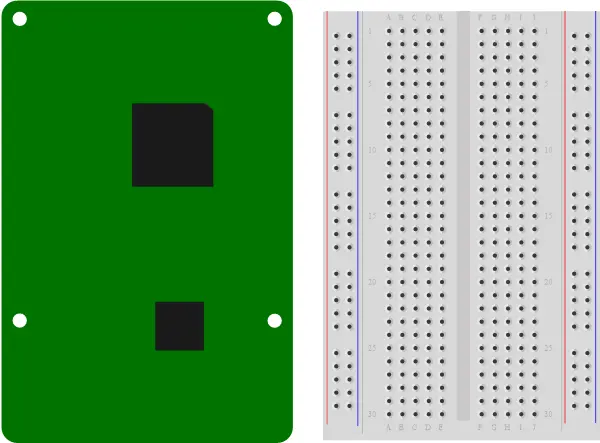
This circuit involves connecting an LED to the always-on 3.3-volt power source on the Raspberry Pi. Please note that pin 1 (+3.3v) on the Raspberry Pi should be connected to the longer leg of your LED. The shorter leg of the LED should be connected to a resistor, which is then linked to pin 14 (ground) on the Raspberry Pi.
Once you have double-checked and confirmed these connections, you can proceed to plug in your Raspberry Pi. At this point, your LED should turn on, indicating that it is functioning correctly. After confirming that the LED operates as expected, unplug your Raspberry Pi.
Next, you will need to move the jumper cable from pin 1 on the Raspberry Pi to pin 36 (GPIO Pin 16) following the illustration provided below: [Illustration would be inserted here, if available]
By following these steps, you will have successfully completed the circuit setup for your LED on the Raspberry Pi.
Once you have successfully installed the “ext/rpi3-gpio16” kernel onto the microSD card, which controls the GPIO pin 16 and alternates its state, you can proceed to plug in your Raspberry Pi with the microSD card inserted. As a result, you should observe your LED initiating a blinking pattern.
Phase 3: Shining C
During this phase, your objective is to write the program that generated the “ext/rpi3-gpio16/kernel8.img” file using the C programming language. You will find the designated location for your code at “tut/1-blinky/phase3/blinky.c”. To compile C and assembly programs specifically for the Raspberry Pi, we will utilize a cross compiler designed for the “aarch64-none-elf” target. This cross compiler can be found in the “bin” directory within the repository.
Talking to Hardware
In modern hardware devices, the primary mode of communication with software is achieved through memory-mapped I/O. The underlying concept is straightforward: devices make their functionality accessible through the system's memory and provide specifications on the actions that occur when certain memory addresses are read from or written to. These memory addresses are often organized into regions of 32 or 64 bits, known as registers. Registers are typically assigned names that reflect their specific functionalities, and they can be categorized as read-only, write-only, or read/write.
The question arises: How do we determine which registers a device exposes, where they are mapped in memory, and what their purposes are? Device manufacturers address these questions by documenting this vital information in various forms such as data sheets, device manuals, or general documentation. However, it is important to note that there is no standardized format for device documentation, and the quality of documentation can vary significantly. Reading and comprehending hardware documentation requires both skill and an understanding of the underlying technology, making it both a science and an art.
GPIO Memory-Mapped Interface
To access the documentation for various peripherals integrated into the Raspberry Pi, you can refer to the Broadcom BCM2837 ARM Peripherals Manual. This manual provides detailed information about the functionalities and specifications of the peripherals. You can locate the manual in the “doc/BCM2837-ARM-Peripherals.pdf” file. For specific details regarding GPIO functionality, you can turn to page 89 of the manual. This documentation serves as a valuable resource for understanding and working with the Raspberry Pi's onboard peripherals.
For this assignment, we’ll only need to use the following three registers:
| name | peripheral address | description | size | read/write |
|---|---|---|---|---|
| GPFSEL1 | 0x7E200004 | GPIO Function Select 1 | 32 bits | R/W |
| GPSET0 | 0x7E20001C | GPIO Pin Output Set 0 | 32 bits | W |
| GPCLR0 | 0x7E200028 | GPIO Pin Output Clear 0 | 32 bits | W |
We’ve copied this information directly from page 90 of the documentation.
To set GPIO pin 16 as an output, we need to refer to the documentation for the GPFSELn register, which can be found on pages 91 and 92 of the Broadcom BCM2837 ARM Peripherals Manual.
In order to set GPIO pin 16 as an output, we need to write a specific value to the corresponding field in the GPFSEL1 register. The exact value and field configuration can be found in the documentation.
Moving on, the GPSET0 and GPCLR0 registers, which are responsible for setting and clearing pins respectively, are documented on page 95 of the same manual.
To set pin 16, we need to write a specific value to the corresponding field in the GPSET0 register. This value and the appropriate field configuration can be found in the documentation.
Likewise, to clear pin 16, we need to write a specific value to the corresponding field in the GPCLR0 register, as specified in the documentation.
By referring to the appropriate sections in the documentation, you will find the exact values and field configurations required to set GPIO pin 16 as an output and to set or clear pin 16 using the GPSET0 and GPCLR0 registers, respectively.
Writing the Code
Within the assignment skeleton, you will find a directory called “tut/1-blinky/phase3/,” which contains the necessary framework for building a binary that is compatible with the Raspberry Pi 3. While the files crt0.S, layout.ld, and Makefile are included in this directory, we will not delve into their explanations at this time. Instead, your focus will be on modifying and working with the blinky.c file within this directory.
Within the blinky.c file, you will notice that the physical addresses of the three relevant registers are declared at the top of the file. Your task is to complete the main() function in order to set up GPIO pin 16 as an output and create a continuous blinking effect by repeatedly setting and clearing the pin. Additionally, rudimentary “sleep” functions have been provided, which allow you to introduce pauses between the pin set and clear operations.
Once you are ready to test your program, you can compile it by executing the “make” command in your shell. If the compilation process is successful, it will generate a file named “blinky.bin,” which represents our initial bare-metal program that can run on the Raspberry Pi. To execute the program on the Raspberry Pi, you need to copy the blinky.bin file as “kernel8.img” to the microSD card, unmount the microSD card, and then insert it back into your Raspberry Pi.
To simplify the process of copying the kernel image to the microSD card, we provide a convenient script called “make install.” You can try executing this script to automatically copy the kernel image to the microSD card.
By following these steps, you will be able to compile and deploy your program on the Raspberry Pi, observing the LED blinking effect once it is running.
If your program blinks the led as expected, proceed to phase 4.
Phase 4: Rusting Away
During this phase, your task is to rewrite the program from phase 3 using the Rust programming language. You can find the designated location for your code at “tut/1-blinky/phase4/src/main.rs”.
It is worth noting that all the necessary programs for your system have already been installed through the bin/setup.sh script. To ensure that everything is in order, it is advisable to double-check the installed programs and their versions. This step will help confirm that you have the required dependencies for Rust development.
By proceeding with the code implementation in the tut/1-blinky/phase4/src/main.rs file and verifying the installation of the necessary programs, you will be able to continue with the Rust-based version of the program.
$ make --version
GNU Make 4.1
...
$ rustc --version
rustc 1.37.0-nightly (0af8e872e 2019-06-30)
$ cargo xbuild --version
cargo-xbuild 0.5.20
$ cargo objcopy --version
cargo-objcopy 0.1.7
That’s it! You have everything ready for this assignment.
Writing the Code
To write the required code in tut/1-blinky/phase4/src/main.rs, you’ll only need to know the following Rust:
- You can read and write from a raw pointer (
*mut T) using the read_volatile() and write_volatile() methods.For example, if we have the following declarations:const A: *mut u32 = 0x12 as *mut u32; const B: *mut u32 = 0x34 as *mut u32;
We can write the 32-bit unsigned integer at address
0x12to0x34with the following:B.write_volatile(A.read_volatile());
- Local variables can be declared with
let variable_name = expression;.Using theAdeclaration from the previous example, we can read the value at address0x12to a local variablevalueas follows:let value = A.read_volatile()
- You can call a function
fn f(param: usize);withf(123);. - A
loopblock can be used to repeat a block infinitely:loop { do_this_again_and_again(); }
- Rust defines the following bitwise operators:
!: unary bitwise inversion<<: left shift binary operator>>: right shift binary operator|: bitwise OR binary operator&: bitwise AND binary operator
You are now at the stage where you can implement the blink program in the tut/1-blinky/phase4/src/main.rs file. Your task is to translate your previous C implementation into Rust within the kmain function. At the top of the file, you will find the declarations of the physical addresses for the three relevant registers. Additionally, we have provided a basic “sleep” function that pauses the CPU for approximately the duration indicated by its name. You can utilize this function to introduce delays between the pin set and clear operations.
Once you are ready to test your program, navigate to the phase4 directory in your shell and compile the code by running the “make” command. If the compilation process completes successfully, it will generate the build/blinky.bin file. To install the blinky.bin file onto the microSD card, you can use the “make install” command.
If your Rust program starts blinking the LED on the Raspberry Pi, it indicates that you have successfully completed assignment 0. You can proceed to the next phase, which will provide instructions for submitting your work.