
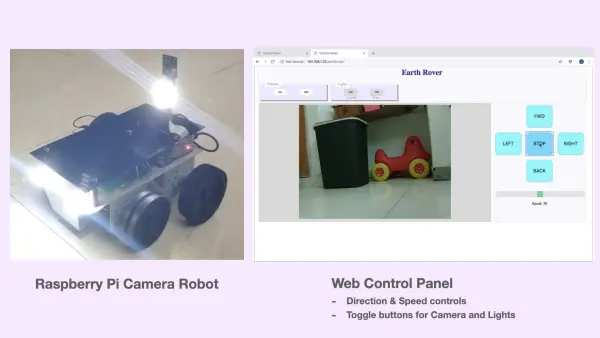
Now that the chassis and motors are installed, it is time to incorporate additional hardware into our Raspberry Pi robot. To add an exciting element, we will develop a web-based mechanism, known as a Web Control Panel, which enables us to control the robot and its associated hardware through a browser. This article provides comprehensive instructions on constructing a camera robot capable of streaming live video to a remote Web control panel accessible via a laptop or smartphone browser.
One of the truly remarkable aspects of the Raspberry Pi is its ability to function like a PC, running sophisticated programs with its modern processor, while simultaneously interacting with external hardware through GPIO pins, akin to a microcontroller.
Leveraging these capabilities, the Raspberry Pi in this Camera Robot project has been assigned the following tasks:
The Raspberry Pi in this Camera Robot project is responsible for the following functions:
- Streaming video using a Python script
- Rendering a web-based graphical user interface (GUI) using PHP, HTML, and JavaScript
- Interfacing with a transistor switching circuit to control 12V high brightness LEDs for lighting purposes.
For this project, the robot is constructed using a Raspberry Pi 3A+, which features a dedicated port for connecting the Pi Camera module. The Raspberry Pi is connected to the following hardware components:
- 3 x 12V LEDs
- 1 x Pi Camera
- BC557 transistors
- 100 ohm resistors
Hardware connections
The previous article discussed the hardware connections, and now those connections have been expanded to accommodate additional hardware components. In this project, three extra GPIO pins are utilized to connect the Raspberry Pi with a Transistor Switching Circuit for controlling 12V LEDs. Since the GPIO pins of the Raspberry Pi operate at 5V, they cannot directly drive the 12V LEDs. To address this, a Switching Circuit is constructed using an NPN Transistor BC547, which can be connected to the Raspberry Pi as illustrated in the provided diagrams.
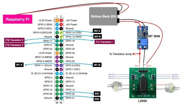
The GPIO pins 17, 18, and 27 are connected to the Transistor Switching Circuit to control the operation of the 12V LEDs.
To recap the other connections:
- GPIO 8, 11, and 20 are responsible for controlling motor 1.
- GPIO 14, 15, and 21 are responsible for controlling motor 2.
- A two-port battery bank supplies power to both the Raspberry Pi and MT 3608 simultaneously.
- The MT 3608 module converts the 5V input supply to the 12V required to operate the motors and illuminate the LEDs.
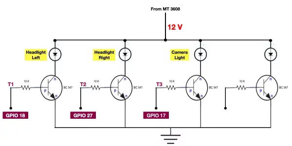
As depicted in the provided diagram, the GPIO pins are connected to the base of the transistors. By manipulating the GPIO pins to a high or low state, we can control the corresponding transistors. The layout of the components on a standard-purpose PCB is illustrated below.
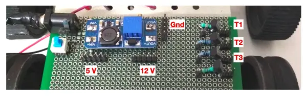
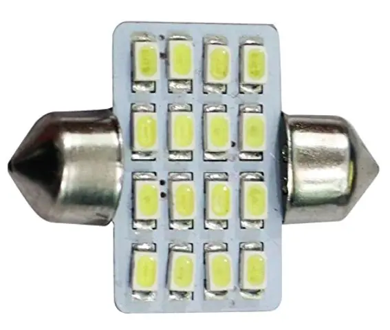
The Camera Robot project utilizes the 12 V high brightness LEDs showcased in the image below.
Testing the connections
To proceed, create a new file called ‘test.py' and replicate the provided Python code. Execute the file using the terminal. You will observe the LEDs blinking at a one-second interval.
import RPi.GPIO as GPIO
from time import sleep # import sleep function from time module
GPIO.setmode(GPIO.BCM) # choose BCM numbering scheme
GPIO.setup(18, GPIO.OUT)# set GPIO 18 as output pin
GPIO.setup(27, GPIO.OUT)# set GPIO 27 as output pin
GPIO.setup(17, GPIO.OUT)# set GPIO 17 as output pin
while True:
GPIO.output(18, True)
GPIO.output(27, True)
GPIO.output(17, True)
sleep(1)
GPIO.output(18, False)
GPIO.output(27, False)
GPIO.output(17, False)
sleep(1)
Camera Setup and Testing
The Pi Camera module is a crucial component of our Camera Robot. Connect the Pi Camera's ribbon cable to the camera port on the Raspberry Pi.
Before using the camera, it's important to ensure that it is enabled. Open the terminal and enter the command “sudo raspi-config”. From there, navigate to the “interfacing options” and enable the camera.
To test the camera from the terminal, use the command “raspistill -o image.jpg”. Alternatively, you can run the provided Python code below to capture an image.
from picamera import PiCamera
from time import sleep
camera = PiCamera()
camera.resolution = (2592, 1944)
camera.annotate_text_size = 100
camera.annotate_text = “Hello world !!!”
camera.rotation =180
camera.start_preview()
sleep(2)
camera.capture(‘/home/pi/Downloads/image1.jpg')
camera.stop_preview()
Video Streaming using Pi Camera
The Camera Robot project requires a live camera feed that can be accessed through a web browser. In my search for an open-source solution, I came across a script in the advanced recipes of the Picamera documentation. This script utilizes Python's built-in http.server module to create a simple video streaming server. By running this script, the camera's video stream can be accessed by visiting “http://ip-address-of-raspberry-pi:8000” using a browser on a PC or mobile device.
The video streaming Python code is contained in the file ‘cam_server.py', located in the ‘earthrover > camera_lights' directory. This code provides an out-of-the-box solution, eliminating the need for any additional coding on your part. All that's left to do is embed the HTML page “http://ip-address-of-raspberry-pi:8000” in our Web Control Panel and create controls to start and stop the video stream. The following section will provide more details on how to accomplish this.
Web Control Panel of Camera Robot
The Web Control Panel of our Camera Robot project has been developed using popular web technologies such as PHP, HTML, and JavaScript. To access the code for this project, you can download the repository from Github. In order to deploy this code and access the Web Control Panel, it is necessary to have a web server running on the Raspberry Pi.
The graphical user interface (GUI) displayed below is generated by the ‘index.php' file located in the ‘earthrover' folder. Take note of the different sections within the Web Control Panel and the corresponding files associated with each section.
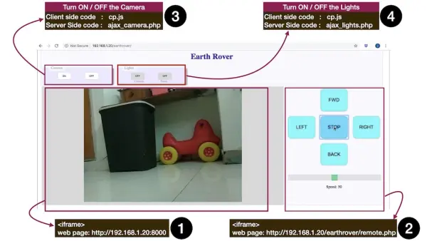
HTML5 offers a simple method to incorporate one web page into another using the <iframe> tag. Sections 1 and 2 of the Web Control Panel are seamlessly embedded within the ‘index.php' file using the following code.
$host=$_SERVER[‘SERVER_ADDR'];//get the sever address. (In my case it is ‘192.168.1.20')
$path=rtrim(dirname($_SERVER[“PHP_SELF”]), “/\\”); //get the name of the directory where this file resides. (In this case it is ‘earthrover')
//URL of remote.php file i.e. http://192.168.1.20/earthrover/remote.php
$link_remote= ‘http://'.$host.$path.'/'.”remote.php”;
//URL of web page generated by ‘cam_server.py' i.e. http://192.168.1.20:8000
$link_vid= ‘http://'.$host.':8000′;
//display the above 02 URLs in this web page
echo”
“;
Section 1 : Display Video Streaming output of Raspberry Pi Camera
The ‘cam_server.py' file is responsible for generating the web page with the video streaming output. As long as this file is active in the background, the video stream can be accessed on a web page. The Web Control Panel incorporates this web page by utilizing the <iframe> tag, as demonstrated in the provided code snippet.
Section 2: Direction and Speed Controls of Camera Robot
The ‘remote.php' file serves the web page that includes the direction and speed controls. The details about the functionality of this file are discussed in a previous article. To incorporate this page into our Control Panel, we can easily embed it using the <iframe> tag, as illustrated in the provided code snippet.
Section 3: Camera ON/OFF controls
Within this section, there are two buttons, namely ‘ON' and ‘OFF', responsible for controlling the camera feed. These buttons are created using the <input> tag within the ‘index.php' file, utilizing the following code. It is important to note that both buttons invoke the same JavaScript function, ‘camera()', but with different parameters. The implementation of this function can be found in the ‘cp.js' file located in the ‘earthrover/js' directory.
The ‘camera()' function is responsible for receiving a parameter (‘on' or ‘off') based on the button pressed. It then sends this value as a POST parameter to the server-side PHP file, ‘ajax_camera.php', through a background AJAX call. The code snippet provided illustrates this process.
function camera(status)
{
//alert(status);
$.post(“camera_lights/ajax_camera.php”,
{
camera:status
}
);
sleep(1000);
location.reload();
}
The ‘ajax_camera.php' file receives the ‘on' or ‘off' value from the previous step and executes an operating system command accordingly. It launches or terminates the execution of the Python script ‘cam_server.py'. This allows for the control of the camera feed based on the received value.
To enable launching or terminating a Python script from a PHP file, you will need to make modifications to the ‘sudoers' file in Raspberry Pi. You can edit the ‘sudoers' file by running the command ‘sudo nano /etc/sudoers' in the terminal. Append the following lines at the end of the file and save it to achieve the desired functionality.
Section 4: Lights ON/OFF controls
Within this section, there are two buttons available: one to toggle the camera LED light and the other to toggle the front LED lights of the robot. These buttons are generated using the <input> tag within the ‘index.php' file, as depicted below. The ‘onclick' event of these buttons invokes a shared JavaScript function called ‘toggle_light()', but with distinct parameters (the button's ID). The implementation of this function can be found in the ‘cp.js' JavaScript file, located in the ‘earthrover/js' directory.
The ‘toggle_light()' function operates by initially toggling the caption and color of the corresponding button, followed by invoking the ‘set_lights()' function with the button's ID and the desired state as arguments. The ‘set_lights()' function, in turn, forwards these two parameters to a PHP file named ‘ajax_lights.php' on the server using an asynchronous background ajax call, as illustrated in the code snippet provided below.
function toggle_light(id)
	{
		button_caption=document.getElementById(id).value;
		if(button_caption=="OFF"){
			document.getElementById(id).value="ON";
			document.getElementById(id).style.backgroundColor="#66ff66";
			set_lights(id,1);
		}
		if(button_caption=="ON"){
			document.getElementById(id).value="OFF";
			document.getElementById(id).style.backgroundColor="lightgray";
			set_lights(id,0);
		}

	}

function set_lights(id,state)
{
		$.post("camera_lights/ajax_lights.php",
		{
		light_id: id,
		state: state
		}
		);

}
The ‘ajax_camera.php' file receives the two parameters (button id and its desired state) via $_POST super global variable. Using these two parameters, it constructs appropriate command to set the corresponding GPIO pins high or low as shown below.
<?php
include_once '../vars.php';

$light_id=$_POST["light_id"];
$state=$_POST["state"];

if ($light_id=="camlight"){
	system("gpio -g write $cameralight $state");
}

if ($light_id=="headlight"){
	system("gpio -g write $headlight_right $state");
	system("gpio -g write $headlight_left $state");
}

echo"$light_id, $state";

?>