Stepper motors are versatile devices that allow precise and repeatable angular control. They are used in disk drives, translation tables, and 3D printers to name just a few applications. They typically come with two different wiring arrangements. The most common arrangement is four wires that are connected to two coils. This is called a bipolar motor and requires something called an “H” bridge to control. The other arrangement is five or six wires. These are called unipolar motors and they’re much easier to drive.
Step 1: Background
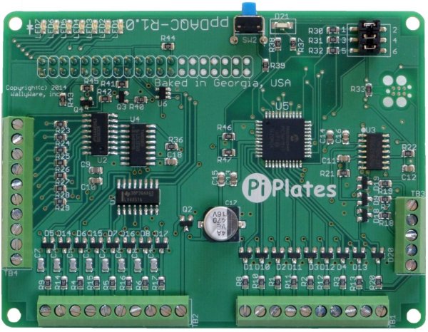
In this example, we will be using four of the seven open collector outputs on a Pi-Plates (Pi-Plates.com) ppDAQC to drive a small, unipolar motor. The motor which can be purchased from Amazon or Adafruit, has the following specifications:
- Unipolar stepper with 0.1″ spaced 5-pin cable connector
- 32 steps per revolution
- 1/16.025 geared down reduction
- 5V-12V DC suggested operation
- Weight: 37 g.
- Dimensions: 28mm diameter, 20mm tall not including 9mm shaft with 5mm diameter
- 9″ / 23 cm long cable
- Holding Torque @ 12VDC: 250 gram-force*cm, 25 N*mm/ 3.5 oz-force*in
- Shaft: 5mm diameter flattened
You will also need your prepared Raspberry Pi to make it all work!
Step 2: Connections
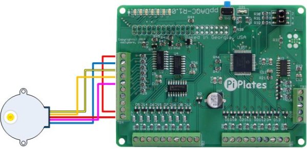
The motor is labeled to operate at 12VDC but to make this easy, we’re going to start by driving it at 5V. Use the enclosed diagram to make your connections.
The connections all go to the DOUT terminal block and are as follows:
- Motor RED wire: Terminal 10
- Motor BLUE wire: Terminal 2
- Motor PINK wire: terminal 5
- Motor ORANGE wire: terminal 4
- Motor YELLOW wire: terminal 3
- Connect a wire from terminal 1 to terminal 9 – this is IMPORTANT since it shunts the inductive kick generated when a coil is turned off.
Using an ohmmeter, we measured about 100 ohms between the red center tap wire and the blue wire. If we use the 5VDC from the ppDAQC and assume that the “on” voltage of the open collector driver is 1 volt then we can calculate that each driver will have to sink about (5-1)/100 = 40mA. So, no special power supplies should be required for this experiment.
Step 3: Code
To determine the driving sequence, we referenced this Application Note from SiLabs. Now, open NANO and enter the following lines of code:
Step 4: Save and Play!
Save your program as UnipolarTest.py and then run it from the command line with the following statement:
sudo python UnipolarTest.py
If everything is correct, you should see your motor shaft rotate counterclockwise for about 16 seconds and then rotate clockwise for 16 seconds. This sequence will repeat until you press <CNTL-C>. While it’s running, try grabbing the shaft. and note that while it is a geared down motor it doesn’t provide a lot of torque at 5VDC. As an experiment, we disconnected the red wires from terminals 9 and 10 and connected them to a 12VDC power supply. Needless to say, the motor torque was substantially higher.
For more detail: Driving a Unipolar Stepper Motor with a ppDAQC Pi-Plate


