
Living in a bustling city often means facing the risk of having your valuable car or motorbike damaged, tipped over, or stolen when parked on the street. Finding a nearby lockup space is a challenge, which is why I've attempted to gather a few components to create a system that can alert me and prompt a response when there's a potential threat to my vehicle.
It's important to note that my motorbike already has a tracker installed, so I'm not aiming to replicate its functionality. Instead, I want to receive additional information about the surroundings.
Here's a checklist of the requirements for the system:
- 4G connectivity since WiFi is not available.
- Sufficient battery life to operate for an extended period of time (recommended reading required).
- Motion detection capability.
- Captures an image when motion is detected.
- Sends me a warning notification via email.
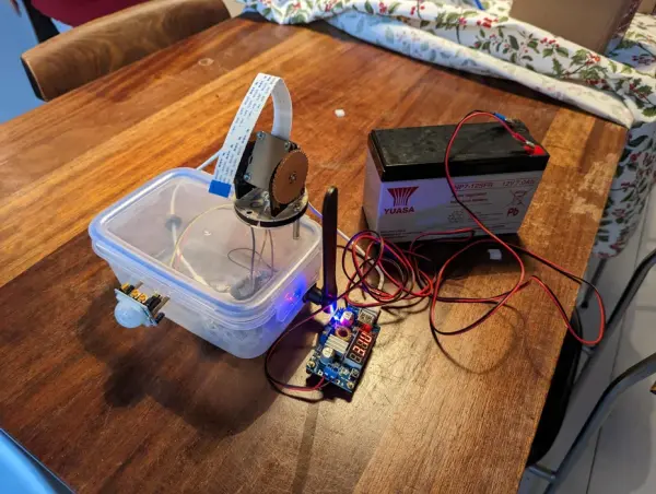
Supplies
- Plastic Tupperware container
- Glass Tupperware container
- Drill bits for creating holes in the Tupperware
- Raspberry Pi Zero 2 (Consider checking Facebook Marketplace due to the current chip shortage)
- 4G hat for mounting on top of the Pi using pins
- Data-enabled SIM card
- 12V rechargeable lead battery
- Crimp connectors for connecting the battery
- Buck power module with USB output to convert 12V battery power to 5V for the Pi
- Raspberry Pi camera
- Holder for the Pi camera
- Motion sensor for the Pi
- GPIO leads for connecting the motion sensor to the Pi
- USB mouse, keyboard, and an HDMI to mini-HDMI adapter
- PCB spacers for mounting components
- Rubber grommets
- Electrical wire
- Breakaway pins for soldering to the Pi
- High-quality soldering iron with a pointed and hot tip for soldering the small Pi pins.
Step 1: Prep Your Containers
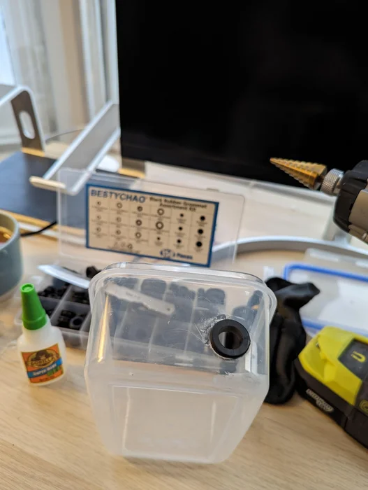
To modify the plastic Tupperware, utilize the drill bit and grommets to create holes for the following components:
- 4G antenna output
- Micro USB power input
- GPIO leads for motion detector output
- Camera output
It's advisable to test the fit of the components before proceeding with drilling holes or soldering spacer screws. Ensure that the chosen mounting location allows for convenient connection of the USB power cable and accessibility to the GPIO pins.
For the glass Tupperware, simply cut openings on the top for the power leads. Use grommets as needed. This container will accommodate the buck module separately to prevent heat interference.
Step 2: Prep Your Pi
Detach two sets of breakaway pins and solder them onto pins 1&2 and 13&14.
The purpose of this will become clear as we proceed with the coding process.
Step 3: Prep Alert Management – AWS
Having some familiarity with Amazon Web Services (AWS) can be helpful for this step, but here's a general overview:
AWS is a cloud computing platform that offers various tools to set up a notification system for our Raspberry Pi. Through AWS, we can establish a communication channel between the Pi and a notification service, which can then relay messages, such as email notifications, as needed. Setting up an AWS account is free, but there may be charges based on your usage.
The basic concept is as follows:
- The Pi sends a message to a notification service topic.
- The topic is configured with a subscription that triggers an action to send an email.
Step 4: Prep Alert Management – Create Topic
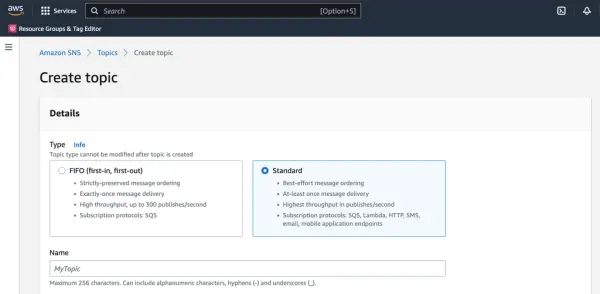
To create topics within AWS, we'll be using the SNS service.
SNS enables us to send messages to a specific topic. Once a message is received by the topic, we can set up a subscription to define the action to be taken. In our case, we want to receive email notifications.
Let's proceed by creating a topic in SNS using the AWS Console (refer to the provided screenshot). You only need to provide the name for the topic, such as ‘garage-motion.'
Important: Remember to select the correct region for your setup. It's crucial to keep the region consistent.
After creating the topic, make a note of its ARN (Amazon Resource Name). We'll need it later in the process.
Step 5: Prep Alert Management – Create Subscription
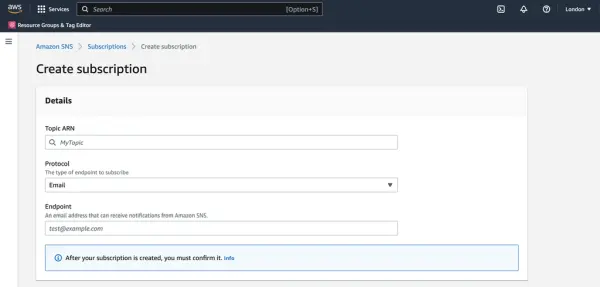
Once again, within the AWS SNS console, proceed to create a Subscription.
From the provided dropdown menu, select your Topic ARN. Choose 'email' as the protocol, and input your email address as the endpoint.
Click on ‘create subscription' located at the bottom of the page.
Now we're prepared to have the Raspberry Pi send messages to AWS, which will then forward them to our specified email address. (Note: You can also choose to send SMS messages and explore other options, but they can be costly.)
Step 6: Pi Zero OS
Use the Raspberry Pi Imager to flash your micro SD card.
It is recommended to choose a Pi OS version that includes a desktop. This is because if you were to connect to the Pi via SSH from another machine to configure networking options for the 4G HAT, the connection would drop and you would be unable to perform any further terminal operations due to the change in IP address and other related factors.
To enable SSH on startup and provide your Wi-Fi credentials, utilize the advanced options cog icon located at the bottom right of the imager. From there, you can configure your wireless LAN and SSH settings.
Once the SD card is installed in the Pi, SSH into it and execute the following command to prepare the GPIO pins:
sudo apt-get install rpi.gpio
Then:
sudo raspi-config
Navigate to the Interface Options menu, then select I2C. Enable I2C by choosing the option for ‘Yes'.
Restart the system.
Once the system has rebooted, repeat the same steps for SPI in the Interface Options.
Restart the system again.
Step 7: Install the AWS CLI
pip3 install awscli
export PATH=/home/pi/.local/bin:$PATH
aws --version
aws configure
You'll be asked to input some details you'll be able to grab from your AWS account
Step 8: Install Some Code Dependencies
mkdir projects && cd &_ && mkdir garage-motion && cd &_ && python3 -m venv venv
Create requirements file:
touch requirement.txt
Add requirements to file:
boto3==1.26.45
botocore==1.29.45
colorzero==2.0
gpiozero==1.6.2
jmespath==1.0.1
python-dateutil==2.8.2
RPi.GPIO==0.7.1
s3transfer==0.6.0
six==1.16.0
urllib3==1.26.13
Activate the venv:
source venv/bin/activate
Install the requirements:
pip install -r requirements.txt
Step 9: Motion Sensor Connections

Ensure that the sensor is oriented with the sensor facing upwards, and connect the GPIO pins as follows:
- Positive 5V: Connect to the 5V pin (pin 2).
- Output: Connect to GPIO27 (pin 13).
- Ground: Connect to the ground pin (pin 14).
Note: Pin configurations may vary, so refer to the PCB or documentation for accurate pin assignments.
Step 10: Motion Sensor and Sending Message
touch garage-motion.py
Open up the file and add the code, being careful of indentation:
import time
import boto3
import RPi.GPIO as GPIO
GPIO.setwarnings(False)
GPIO.setmode(GPIO.BOARD)
GPIO.setup(13, GPIO.IN) # Middle pin defined in Step 9

client = boto3.client('sns')

while True:
    i=GPIO.input(13)
    if i==0: # When output from motion sensor is LOW
        print("No intruders",i)
        time.sleep(0.1)
    elif i==1: # When output from motion sensor is HIGH
        print("Intruder detected",i)
        response = client.publish(
            TargetArn='yourSNSTopicARN',
            Subject='Garage update',
            Message="Yo, you got movement",
            MessageStructure='string'
        )
        print(response['MessageId'])
    time.sleep(0.1)
Remember to replace the topic ARN from Step 4 here.
Next step is to run the script:
python3 garage-motion.py
Stand in front of the motion sensor to test its functionality and trigger an email notification. It is recommended to adjust the potentiometers on the motion sensor and rerun the script.
The right potentiometer controls the sensitivity, while the left potentiometer adjusts the timeout duration. Turning them fully anti-clockwise sets the sensitivity and timeout to their lowest levels.
With the timeout turned fully anti-clockwise, the sensor will produce a signal for approximately 2.5 seconds upon detecting motion. When the potentiometer is turned fully clockwise, the signal will last for around 250 seconds. It is advisable to fine-tune the sensitivity while keeping the timeout duration as low as possible.
Step 11: Time for Local Pi Development!
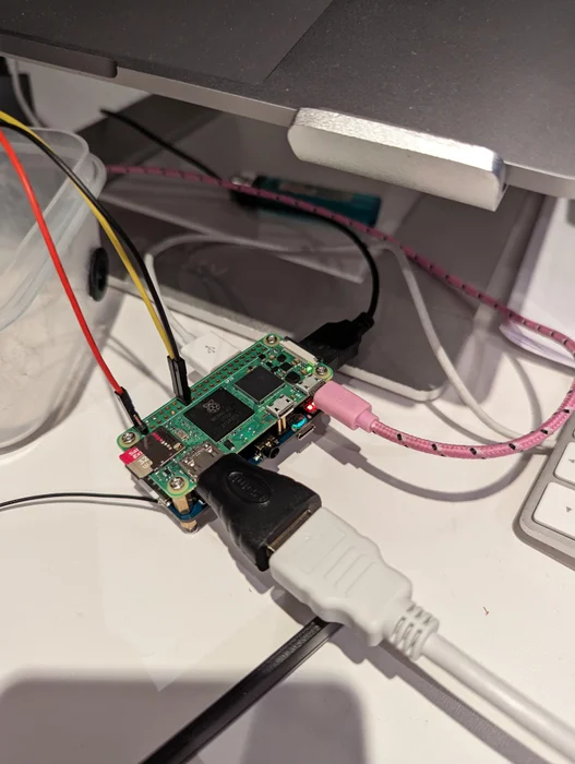
Next, we will proceed to install the 4G hat on the Raspberry Pi, but please note that once it's configured, the SSH connection will be lost as the traffic won't route through the wireless interface anymore.
Here are the steps to follow:
- Insert your SIM card into the slot on the 4G hat (e.g., using a Things Mobile SIM).
- Securely attach the hat to the Raspberry Pi, ensuring that the pins align properly with the GPIO board.
- Connect your USB mouse and USB keyboard to the ports on the hat.
- Connect the HDMI mini output to the Pi for display.
- Establish a connection between the GPIO pins of the sensor and the Pi.
- Power up the Pi by connecting it to a USB power source, and treat it like a computer by using the mouse, keyboard, and display.
- Open a terminal window to proceed with further instructions.
Step 12: Make the Network Changes to the Pi to Allow Traffic to Be Routed Through the Hat (not Wifi)
This step can be quite involved, especially if you're not familiar with networking. However, I found that the software setup step from Twilio closely resembles what we need to do for this project.
Since you have already connected the hat to the Pi Zero using the pins, you can skip ahead to the software step.
You don't actually need to open a browser at the end of those steps to confirm the connection, as it can be quite slow. Simply running the command ‘ping apple.com' in the terminal window should be sufficient.
Now, we need to automate the last two steps so that they run on boot: starting ‘pon' in the background and updating the route table for ‘ppp0'. Finally, we'll run the Python script.
To achieve this, we'll break it down into three parts:
- Creating a service that starts ‘pon' in the background.
- Updating the route table for ‘ppp0'.
- Configuring the Python script to run.”
Note: The paraphrased version assumes prior knowledge of the Twilio setup and the steps involved.
1. Pon service
To do this we will use the pi's systemd services which run at startup.
Let's create a service:
sudo touch /etc/systemd/system/4gpon.service
Give it the correct permissions:
sudo chmod 644 /etc/systemd/system/4gpon.service
Then we add what we want it to do:
sudo nano /etc/systemd/system/4gpon.service
Then add the following:
[Unit]
Description=4G hat networing

[Service]
Type=forking
ExecStart=/usr/bin/pon
ExecStop=/usr/bin/poff
Restart=always

[Install]
WantedBy=multi-user.target
Then we tell the pi to use this script on startup:
sudo systemctl enable 4gpon.service

Reboot the Raspberry Pi and open a terminal window.
ps aux | grep pon
and this should show the process running the background. Nice.
2. Update route table
Executing these commands will remove the default route and replace it with the ppp0 interface for the Raspberry Pi, making it the new default.
sudo ip route delete default
sudo ip route add default dev ppp0
Then we want to add an actual ppp0 interface
sudo nano /etc/network/interfaces.d/ppp0
Then add to the file:
auto ppp0
iface ppp0 inet provider
up ip route add default dev ppp0
We have one more thing to add into the provider we would have touched on in the Twilio steps…
sudo nano /etc/ppp/peers/provider
Add at the bottom:
replacedefaultroute
3. Motion service
Similar to the previous step, we will now create a systemd service to run the script on startup, ensuring that the network is up before executing. systemd services are designed to handle dependencies and ensure proper execution. Let's proceed with creating the service:
sudo touch /etc/systemd/system/garage-motion.service
Give it the correct permissions:
sudo chmod 644 /etc/systemd/system/garage-motion.service
Then we add what we want it to do:
sudo nano /etc/systemd/system/garage-motion.service
with:
[Unit]
Description=Motion detector service
After=network.target network-online.target 4gpon.service

[Service]
Type=simple
Environment="AWS_DEFAULT_REGION=***your-region***"
Environment="AWS_ACCESS_KEY_ID=***your-key***"
Environment="AWS_SECRET_ACCESS_KEY=***your-secret-key***"
ExecStart=/bin/sh -c '/home/pi/projects/garage-motion/venv/python3 /home/pi/projects/garage-motion/venv/garage-motion.ph --serve-in-foreground'
Restart=on-abort

[Install]
WantedBy=multi-user.target
Let's start the service:
sudo systemctl start garage-motion.service
To check that the service is up, you can do:
sudo systemctl status garage-motion.service
Check if you get an email from the script!
Then we tell the pi to use this script on startup:
sudo systemctl enable garage-motion.service
Lastly, we need to ensure that the desktop display doesn't interfere with the startup of services. So far, the Raspberry Pi has been assuming that we are using a desktop setup and initializes services when an HDMI display is detected.
To resolve this, use the command sudo raspi-config to set a forced screen resolution. Select any resolution other than the monitor default option.
Afterward, shut down the Raspberry Pi by running sudo shutdown now. You're now ready to take your setup into the world and give it a try!
Step 13: Battery and Buck Module
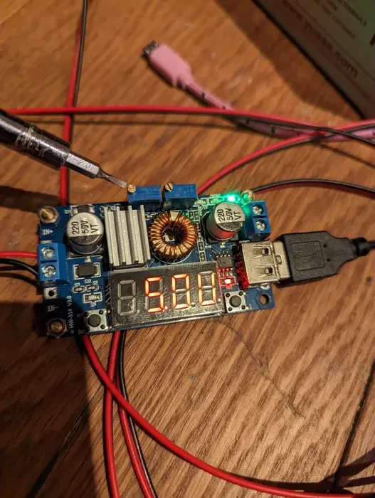
Crimp your connectors for the battery on the wires. Connect the other end of your wires to the buck module.
CONNECT NOTHING TO YOUR BUCK MODULE OUTPUT (yet)
The position of the voltage screw that determines the output voltage (and current to some extent) is unknown. There is a risk of damaging your device if you connect it to a higher voltage. Therefore, it is crucial to initially set the voltage screw to its minimum position by turning it fully counterclockwise.
Next, connect a device that you don't mind potentially damaging, such as a fan shown in the provided pictures.
The voltage needs to be adjusted accurately, while the current will adjust itself based on the device's requirements. To set the voltage to 5.1V, use a screwdriver on the left blue component indicated in the diagram.
Step 14: Bonus – Added Camera
If you want the additional security of capturing a camera image when the motion detector is triggered, follow these steps:
- Connect the camera to your setup.
- Enable the camera interface by accessing the sudo raspi-config menu and enabling it in the interfaces section.
- Refer to a guide on setting up openCV to configure the camera functionality.
- Set up an Amazon S3 bucket with public permissions.
- Modify the Python script to include code for uploading an image to the S3 bucket and include the image's path in the email notification. This will allow you to view the image immediately when you receive the email.
from datetime import datetime
import time
import boto3
import RPi.GPIO as GPIO
import cv2

GPIO.setwarnings(False)
GPIO.setmode(GPIO.BOARD)
GPIO.setup(13, GPIO.IN) # Middle pin defined in Step 9


client = boto3.client('sns')
s3_client = boto3.client('s3')


while True:
    i=GPIO.input(13)
    print(f'Sensitivity: {i}')
    if i==0: # When output from motion sensor is LOW
        print("No intruders",i)
        time.sleep(0.1)
    elif i==1: # When output from motion sensor is HIGH
        print("Intruder detected",i)
        now = datetime.now()
        date_time = now.strftime("%m%d%Y-%H%M%S")
        # camera bits
        cap = cv2.VideoCapture(0)
        ret, frame = cap.read()
        if ret:
            cv2.imwrite(f'intruder-{date_time}.jpg', frame)
        cap.release()
        del(cap)
        s3_client.upload_file(
            Filename=f'/intruder-{date_time}.jpg',
            Bucket='your-s3-bucket',
            Key=f'intruder-{date_time}.jpg'
        )
        # SNS send
        response = client.publish(
            TargetArn='your-arn',
            Subject='Garage update',
            Message=f'Yo, you got movement: https://your-s3-bucket.s3.eu-west-2.amazonaws.com/intruder-{date_time}.jpg',
            MessageStructure='string'
        )
        print(response['MessageId'])
    time.sleep(0.1)