Embarking on a Raspberry Pi journey can be a thrilling endeavor, especially for beginners. The accessibility of coding and do-it-yourself electronics has never been greater.

A straightforward project involves creating a basic circuit with two LEDs and using code to control one of them. Let's dive into the step-by-step process!
Required Components
Prior to getting started, it's important to ensure that your Raspberry Pi has an operating system installed. The quickest and simplest way to accomplish this is by installing Raspbian through the NOOBS (New Out Of the Box Software) package.
Once your Pi is powered on, connect it to a screen, mouse, and keyboard as you would with a regular desktop computer. Alternatively, you have the option to establish a connection via SSH (Secure Shell) to reduce the clutter of additional wires. Regardless of the method you choose, we will guide you on how to control the LEDs effectively.
Before proceeding with circuit construction, it's recommended to power off your Raspberry Pi to avoid any potential damage.
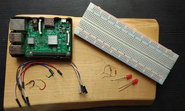
In addition to your Raspberry Pi, gather the following components:
- Breadboard
- 2 x LEDs
- 2 x Resistors (anywhere from 220 Ohm to 1 kOhm)
- Hookup cables
If you acquired a Raspberry Pi starter kit, you likely already have all the necessary components at your disposal. Now, let's proceed to build our circuit.
A Simple LED Circuit
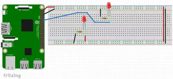
Arrange your components according to the provided Fritzing diagram below:
(Unfortunately, as a text-based AI, I'm unable to display or interpret visual diagrams. However, you can easily find Fritzing diagrams online or refer to the specific diagram you have for proper component placement.)
The circuit configuration serves two purposes. Firstly, the 5V and GND pins of the Raspberry Pi are connected to the Power Rails of the breadboard.
Note: If you're unfamiliar with breadboards and how they function, you can refer to our comprehensive breadboard crash course for a better understanding.
The two power rails on the breadboard are interconnected at one end, and a wire extends from the positive power rail to the positive (anode) side of the lower LED. The negative side of the LED is linked to a resistor, which is then connected back to the GND power line.
On the other hand, the upper LED follows a different wiring scheme. A wire originates from pin 12 (GPIO18) of the Raspberry Pi and connects to the positive side of the LED. It then traverses through the resistor and returns to the GND rail. Despite the seemingly confusing fact that pin 12 is also referred to as GPIO18, our guide on Raspberry Pi GPIO pins can provide clarity on this matter.
While the orientation of the resistors is not critical, correctly positioning the LEDs is crucial. Fortunately, determining the correct polarity of the LED terminals is straightforward:

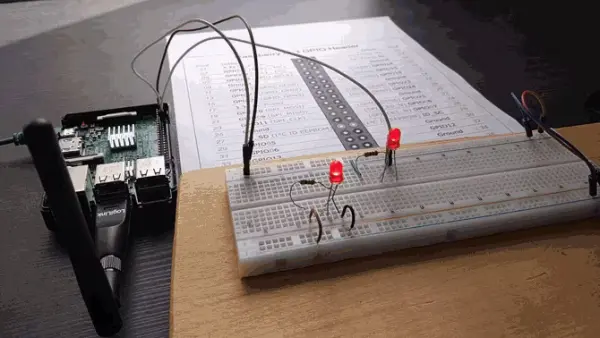
After successfully arranging all the components, your circuit should resemble the following image:
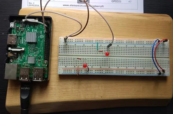
Please ensure that your setup is accurate, and then power on your Raspberry Pi. The LED connected directly to the 5V pin should illuminate instantly. The second LED, which you will control through code, is the one to focus on.
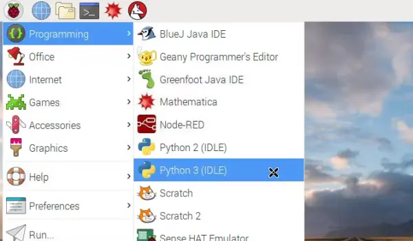
Method 1: Python via IDLE
If you're utilizing your Raspberry Pi in desktop mode, access the applications menu located at the top left of your screen, then navigate to Programming > Python 3 (IDLE). This will launch the Python shell. If you're operating in SSH mode, instructions on how to proceed will be provided later in the article.
The Raspbian operating system includes Python as a pre-installed programming language. Python is an excellent choice for beginners, and there are numerous helpful websites available to assist you in getting started. In this tutorial, we will create a Python script together. However, if you prefer to obtain the complete script, you can copy the code from Pastebin.
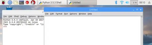
While it is possible to write code directly in the Python shell, it would be beneficial to create a program that can be saved and reused. To do so, open a new file by navigating to File > New File.
To get started, you'll create a basic blink sketch that will alternate the LED between on and off states. The first step is to import the RPi.GPIO and time modules.
import RPi.GPIO as GPIO
import time
By importing RPi.GPIO as GPIO, you can save yourself from typing “RPi.GPIO” every time you reference the module. Additionally, the time module is necessary to introduce delays between turning the LED on and off. Next, you'll proceed to set up the GPIO pin.
GPIO.setmode(GPIO.BOARD)
GPIO.setwarnings(False)
ledPin = 12
GPIO.setup(ledPin, GPIO.OUT)
Configure the GPIO pins to use the BOARD numbering system and disable GPIO warnings. If you find this concept difficult to grasp at this point, don't worry, as it will become clearer with further experience. Afterward, assign the value 12 (GPIO18) to the ledPin variable, indicating that it corresponds to pin 12 on your Raspberry Pi. Finally, configure the ledPin as an OUTPUT pin, ensuring that it is ready to control the LED.
Making the LED Light Flash
To control the number of times the LED flashes, you can utilize a for loop. Enter the following code, ensuring that it is indented in the same manner.
for i in range(5):
print(“LED turning on.”)
GPIO.output(ledPin, GPIO.HIGH)
time.sleep(0.5)
print(“LED turning off.”)
GPIO.output(ledPin, GPIO.LOW)
time.sleep(0.5)
The for loop in this code will iterate five times. Each iteration will display a message in the Python Shell, followed by setting pin 12 to HIGH, turning on the LED, and then setting it to LOW to turn off the LED. Finally, the program will automatically terminate.
Save your program and choose Run > Run Module from the editor menu. You should observe your LED flashing five times.
Congratulations! You have created your first GPIO program!
Method 2: Python via SSH and Nano
If you are connected to your Raspberry Pi via SSH, you can create this program directly from the command line. Use the Nano text editor to create a new script by typing the following command:
sudo nano blink.py
This will open a new file named “blink.py” in the Nano editor. Enter the code exactly as mentioned before, ensuring proper indentation. Save the program by pressing Ctrl-X, which will prompt you to save at the bottom of the screen.
Type “y” to save the file, and then press Enter to confirm the filename. This will return you to the command line. You can execute your program using the Python command:
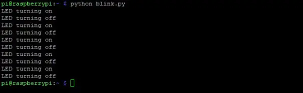
python blink.py
Upon running the program, you will observe the LED flashing and the corresponding output displayed on the screen.