
The Raspberry Pi is widely recognized as the most popular single-board computer. Given its nature as an embedded microcomputer, the acquisition of data is almost indispensable in Raspberry Pi. While the Pi is equipped with several GPIO (General Purpose Input/Output) pins, it lacks a built-in or onboard analog-to-digital converter. Consequently, the Pi itself cannot directly gather data from analog sensors. Analog sensors are commonly employed in embedded applications, and many sensors, such as light-dependent resistors (LDRs) and IR sensors, solely exist in analog form. To address this, there are two methods for connecting analog sensors to the Raspberry Pi. The first approach involves utilizing an external analog-to-digital converter, while the second method entails sampling data from analog sensors using a microcontroller and transmitting all the captured data to the Raspberry Pi via a serial interface.
Using a microcontroller solely for retrieving analog data and interfacing it with the Raspberry Pi is not a practical solution. When the Raspberry Pi operates as an independent embedded microcomputer and analog data acquisition is necessary, employing an external ADC is the most suitable approach.
Analog data acquisition on the Raspberry Pi offers several advantages. Applying machine learning algorithms and deep learning models is considerably easier on a microcomputer like the Raspberry Pi compared to a microcontroller. Microcontrollers are significantly resource-constrained and have limited software tools and APIs for implementing machine learning algorithms or incorporating deep learning networks. The available software tools for machine learning and deep learning on microcontrollers also have limitations in terms of capabilities. For instance, computer vision applications typically require ample RAM and efficient camera sensors for practical implementation. The machine learning tools available for microcontrollers are not sufficiently performant for resource-intensive embedded applications of this nature.
In this project, we will delve into the process of conducting analog data acquisition on the Raspberry Pi by utilizing ADC chips such as ADS1115 or ADS1015. Additionally, we will explore the methodology of reading analog data from IR sensors on the Raspberry Pi. This particular application of reading analog data from IR sensors will be focused on obstacle detection within a Raspberry Pi robot.
Components required
- Raspberry Pi 3B/4B x1
- ADS1115/ADS1015 ADC x1
- IR sensors x1
- Breadboard x1
- Connecting wires/Jumper wires
ADS1115/ADS1015 Pi Vs. microcontrollers
As previously mentioned, there are two methods available for sampling analog data on the Raspberry Pi. Before delving into the usage of external ADCs like ADS1115/ADS1015, it is important to understand the distinction between these two approaches. When we interface a microcontroller such as an Arduino board with the Raspberry Pi, we essentially connect a separate embedded solution to the microcomputer. It's crucial to exercise caution when operating the Arduino board at a different voltage level, as most Arduino boards operate at 5V. In such cases, it is advisable to employ a TTL logic level converter between the microcontroller and the Raspberry Pi to prevent any potential damage to the Pi or its board pins. Conversely, when utilizing an external ADC, we can power the ADC directly from the voltage outputs of the Raspberry Pi, simplifying the setup process.
A microcontroller operates independently with its own data sampling cycle. In such cases, a Python script running on the Raspberry Pi must keep up with the sampling speed of the microcontroller. It's important to note that in this setup, the microcontroller retains control over data acquisition, rather than the Raspberry Pi. This arrangement can be advantageous in time-critical applications where sensor data needs to be promptly processed for quick responses.
On the other hand, when using an ADC, the data acquisition and sampling rate are controlled by the Raspberry Pi itself. Some developers may express concerns that the Raspberry Pi, running a full-fledged operating system, might experience delays in acquiring and processing analog data with external ADCs due to other processes potentially overriding the currently running Python scripts. However, this issue can be easily resolved by implementing parallel threading and employing multi-threading techniques, allowing for the concurrent sensing of analog data in a separate thread.
A microcontroller should only be employed alongside the Raspberry Pi when there is a necessity for executing multiple time-critical embedded tasks concurrently. In such scenarios, the Raspberry Pi can be utilized in the background to carry out extensive data analytics, implement machine learning or deep learning models on sensor data, handle communication with cloud platforms, and manage Internet of Things (IoT) operations.
ADS115/ADS1015 ADC
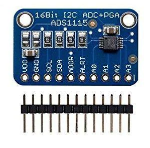
ADS1015 and ADS1115 are analog-to-digital converters known for their low power consumption and high precision. These chips are commonly utilized in conjunction with Raspberry Pi due to their compatibility with the Pi's 3.3V voltage level. The ADS1015 is a 12-bit ADC with four analog input channels, while the ADS1115 is a 16-bit ADC with four analog input channels.
In this project, we will specifically be utilizing the ADS1115. This chip offers support for two types of data acquisition: single-ended and differential. In single-ended conversion, each of the four analog input pins independently samples analog data. On the other hand, the differential mode of operation involves sampling the voltage difference between two analog input pins. The ADS1115 has a resolution of 16 bits, with one bit reserved for indicating the plus/minus sign of the voltage difference in differential mode, leaving 15 bits for storing the converted voltage values. The chip employs an I2C interface for serial data communication with a microcomputer or microcontroller.
The ADS1115 allows the sampling rate to be configured anywhere between 8 and 860 samples per second. A higher sampling rate results in faster capture and conversion of the analog signal. Additionally, the chip incorporates a built-in gain amplifier, which can amplify weak voltage signals by 2-3x up to 16x. The conversion process, whether single-ended or differential, can be carried out in two different ways. In one method, the Raspberry Pi (or controlling microcomputer/microcontroller) initiates the conversion, and the resulting converted value is stored in a register on the ADS1115. The Raspberry Pi then reads the register to obtain the converted value. In the second method, the ADS1115 continuously performs the conversion. The signal is sampled at a predetermined rate (ranging from 8 to 860 samples per second), and the converted value is repeatedly updated in a register on the ADS1115. The Raspberry Pi must read the ADS1115 register repeatedly at the programmed sampling rate. If the Raspberry Pi reads the register at a lower rate, it may miss several captured samples. Conversely, if it reads the register at a higher rate, it will log redundant values for the same samples.
Wiring ADS115/ADS1015 with Raspberry Pi
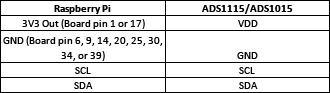
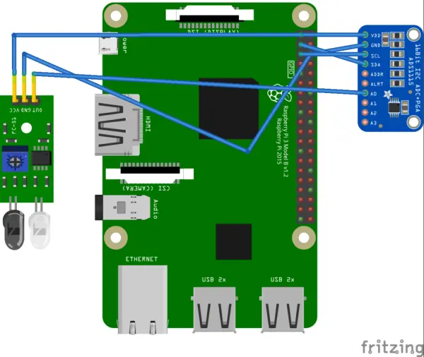
ADS1115 and ADS1015 are responsible for sampling analog data from sensors and transmitting the converted values to the Raspberry Pi via the I2C interface. These chips share the same pin configuration and utilize the I2C protocol. To establish the connection between the ADS1015/ADS1115 and the Raspberry Pi, refer to the circuit connections outlined in the following table.
Enabling I2C on Raspberry Pi
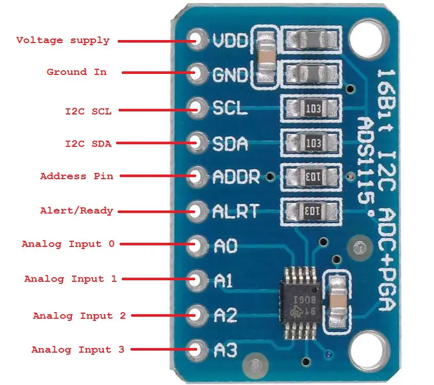
To connect a sensor to the ADS1015/ADS1115, you need to link its analog output to one of the A0, A1, A2, or A3 pins on the ADC chip. It is possible to connect a maximum of four sensors to the ADS1015/ADS1115. The sensor can be powered by the Raspberry Pi itself, but if an external power supply is used, it should not exceed 3.3V to ensure compatibility.
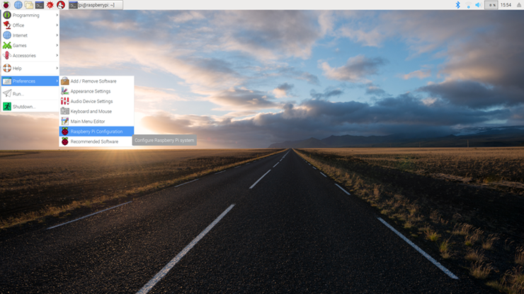
Communication between the ADS1015/ADS1115 and the Raspberry Pi occurs through the I2C protocol. Before interfacing the ADC chip with the Raspberry Pi, you need to ensure that the I2C port is enabled on the microcomputer. To do this, navigate to Preferences -> Raspberry Pi Configuration and make the necessary settings.
A configuration window will open, as shown below.
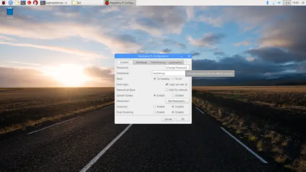
Select the Interfaces tab. Enable I2C and click ok.
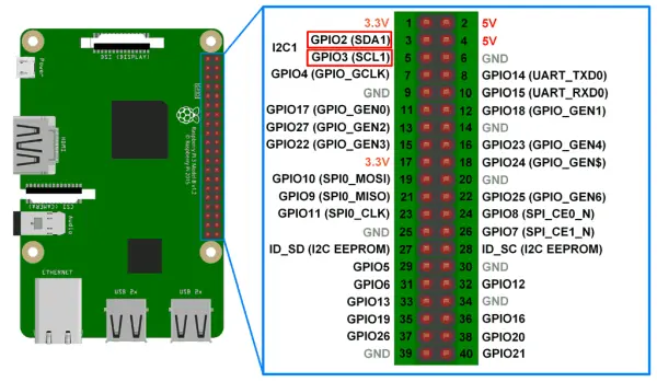
That’s It. Now Raspberry Pi can communicate over an I2C port. The I2C port in Raspberry Pi is shown in the image below.
To explore further about I2C communication in Raspberry Pi and gain a deeper understanding of how the I2C protocol operates, you may find it beneficial.
Fortunately, there is an available Python library called Adafruit ADS1x15 that is specifically designed to work with ADS1015 and ADS1115. This library eliminates the need to write Python scripts from scratch for interfacing with the ADS1015/ADS1115 on the Raspberry Pi.
You can install the Adafruit ADS1x15 Python library on the Raspberry Pi either manually or through the PiP package manager. To install the library from source, open the Bash Terminal by navigating to Accessories -> Terminal or simply clicking on the Terminal icon. Then execute the following commands:
“`bash
sudo apt-get update
sudo apt-get install build-essential python-dev python-smbus git
cd ~
git clone https://github.com/adafruit/Adafruit_Python_ADS1x15.git
cd Adafruit_Python_ADS1x15
sudo python setup.py install
“`
To install the library using the PiP package manager, open the Bash Terminal and execute the following commands:
“`bash
sudo apt-get update
sudo apt-get install build-essential python-dev python-smbus python-pip
sudo pip install adafruit_ads1x15
“`
If you are using Python 3, you need to install the library using pip3 as follows:
“`bash
sudo pip3 install adafruit_ads1x15
“`
Once the library is successfully installed in your Python environment, you can start using it by importing the library in your script. Use the following statement to import the Adafruit_ADS1x15 library:
“`python
import Adafruit_ADS1x15
“`
After importing the library, you need to instantiate an object of the Adafruit_ADS1x15 class. Here's an example statement to create an instance named ‘adc':
“`python
adc = Adafruit_ADS1x15.ADS1115()
“`
By following these steps and utilizing the library, you can easily implement analog data acquisition using the ADS1115/ADS1015 in your Python script.
adc = Adafruit_ADS1x15.ADS1115()
Afterwards, it is necessary to configure the gain for the built-in amplifier. The gain setting should align with the desired sensing voltage range, as indicated in the Programmable Amplifier Gain table found in the datasheet of ADS1015/ADS1115. A convenient summary of the amplifier gain options and their corresponding sensing voltage ranges is presented in the following table.
![]()
To configure the gain for the ADS1115/ADS1015, you can utilize the following statement:
GAIN = 1
The converted voltage reading from the ADC will range from -32768 to +32767 for the ADS1115 and -2048 to +2047 for the ADS1015. A value of 0 corresponds to the ground level. The actual voltage being sensed is determined by the voltage range established by the amplifier gain. For instance, if the gain is set to 1 for the ADS1115, a value of 32767 represents a voltage of 4.096V. Any value within the range of -32768 to 32767 corresponds to an analog voltage given by (4.096/32767) * a.
To read the analog input from A0 of the ADS1115/ADS1015, you can employ the following statement in your Python script.
To read analog values from the ADS1015/ADS1115, you can utilize the following statements:
“`python
value = adc.read_adc(0, gain=GAIN)
“`
Similarly, for analog inputs A1 to A3 on the ADS1015/ADS1115, you can use the following statements:
“`python
value = adc.read_adc(1, gain=GAIN)
value = adc.read_adc(2, gain=GAIN)
value = adc.read_adc(3, gain=GAIN)
“`
In these statements, ‘value' is a variable in your Python script that will store the ADC readings. If you have multiple analog sensors connected to the Raspberry Pi via the ADS1015/ADS1115, you can fetch the ADC readings in a loop. The actual voltages can be calculated using the equation mentioned previously. Here's an example of calculating the actual voltage reading:
“`python
GAIN = 1
value = adc.read_adc(0, gain=GAIN)
analog_voltage = value * (4.096 / 32767)
“`
To interface IR sensors with the Raspberry Pi using the ADS1015/ADS1115, you can follow these steps. IR sensors are typically available only in analog form and are commonly used in Raspberry Pi robots for tasks like line following or obstacle detection. The IR sensor has three pins: VDD, GND, and Out. Connect the Out pin of the IR sensor to any analog input pin on the ADS1015/ADS1115, and supply the positive and negative power to the sensor from the Raspberry Pi itself. Then, interface the ADS1015/ADS1115 with the Raspberry Pi as described earlier. This way, an analog IR sensor can be successfully connected to the Raspberry Pi.
To read the output of an IR sensor in Raspberry Pi, you can execute the following Python script in the console:
“`python
import time
import Adafruit_ADS1x15
adc = Adafruit_ADS1x15.ADS1115()
# Choose a gain of 1 for reading voltages from 0 to 4.09V.
# Or pick a different gain to change the range of voltages that are read:
# – 2/3 = +/-6.144V
# – 1 = +/-4.096V
# – 2 = +/-2.048V
# – 4 = +/-1.024V
# – 8 = +/-0.512V
# – 16 = +/-0.256V
# See table 3 in the ADS1015/ADS1115 datasheet for more info on gain.
GAIN = 1
while True:
value = adc.read_adc(0, gain=GAIN)
print(value)
time.sleep(0.5)
“`
When running this script, the IR sensor outputs a higher voltage when there is no obstacle in its path. When an obstacle blocks the IR sensor, its output voltage is reduced. The ADC readings obtained when there is no obstacle in the path of the IR sensor typically range from 24550 to 24729. With an amplifier gain of 1, these readings correspond to a voltage range of approximately 3.06V to 3.09V. On the other hand, when an obstacle blocks the IR sensor, the ADC readings typically range from 660 to 670. With an amplifier gain of 1, these readings correspond to a voltage range of approximately 0.081V to 0.083V. It's worth noting that the output of the IR sensor can vary based on its calibration using the onboard potentiometer.
Conclusion
The ADS1015 and ADS1115 are analog-to-digital converters with low power consumption and high resolution. They can be easily connected to the Raspberry Pi and communicate using the I2C protocol. These ICs have the capability to simultaneously sense up to four analog voltages in a single-ended configuration. This feature makes the ADS1015 and ADS1115 ideal choices for integrating ADC functionality into Raspberry Pi robots.