
Enabling remote monitoring and control of the GPIO pins on your Raspberry Pi through the web is a great way to enhance the capabilities of your projects. This article focuses on demonstrating how to set up a web server on your Raspberry Pi that can receive REST API calls in JavaScript. It will also guide you on how to utilize these calls to control a servo motor. By following these instructions, you will be able to establish a web-based interface for interacting with and managing your Raspberry Pi's GPIO pins.
Let’s get started with setting up our server environment..
- Install Node.js
- Create a new directory/folder (e.g. “myServo”) for your project and open it up
12
mkdirmyServocdmyServo - Using the Node Package Manager (npm) of Node.js, install express and connect (find “express” in the link for more infomation) in the folder
123
npm initnpminstallexpress --savenpminstallconnect --saveThis code snippet initialize npm in the current folder (../myServo) to install the express and connect packages
Setting up the Servo
What is a Servo
A servo motor is a rotary actuator commonly used by hobbyists that allows us to control the position of its shaft. By providing a Pulse Width Modulated (PWM) signal, the internal control circuit of the servo motor rotates the shaft to the desired position indicated by the width of the PWM signal, and it maintains that position.
The servo motor expects to receive a pulse approximately every 20 milliseconds. The duration of the pulse determines the position of the servo. For example, if the pulse is high for 1 millisecond, the servo angle will be zero. If the pulse is 1.5 milliseconds, the servo will be at its center position. Finally, if the pulse is 2 milliseconds, the servo will be at a 180-degree angle. For more detailed information, you can refer to the provided link.
Attach Servo to Raspberry Pi
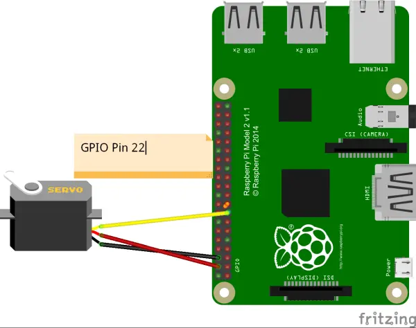
In this tutorial, we will be connecting the control cable of the servo motor to GPIO pin 22 on the Raspberry Pi. It's important to refer to the datasheet of your specific servo motor to identify the control cable, which is typically colored orange or yellow. The datasheet will provide the necessary information on pin configurations and cable identification to ensure correct connectivity.
(Install fritzing to create similar images of circuits)
Pi-Blaster
To generate Pulse Width Modulation (PWM) signals, we will install a tool called Pi-Blaster. Pi-Blaster is a C-based program that enables us to control PWM signals on GPIO ports. It also provides a JavaScript library that allows us to control PWM signals directly from our JavaScript code.
To get started, we need to fetch the source code for Pi-Blaster from Github. Github is a collaborative platform where individuals can collaborate on software development projects and share their code with others.
|
1
2
3
|
cdgit clone https://github.com/sarfata/pi-blaster.gitcd pi-blaster |
By default, Pi-Blaster creates 8 PWM pins, utilizing GPIO pins 4, 17, 18, 21, 22, 23, 24, and 25. This configuration means that these GPIO pins cannot be used for other functions, such as general-purpose input/output (GPIO) operations. To address this, we need to modify the source code of the cloned Pi-Blaster file on our Raspberry Pi.
To make the necessary changes, open the pi-blaster.c file and locate the list of GPIO pins, which should be around line 50.
|
2
3
4
5
6
7
8
9
10
11
12
13
|
// Created new known_pins with raspberry pi list of pins // to compare against the param received. static uint8_t known_pins[] = { 4, // P1-7 17, // P1-11 18, // P1-12 27, // P1-13 21, // P1-13 22, // P1-15 23, // P1-16 24, // P1-18 25, // P1-22 }; |
This section of the code is responsible for defining the pins that will be utilized by Pi-Blaster. To ensure that only the desired pins are included, we need to modify this code accordingly. In our case, we only want to include pin 22.
Therefore, we will modify the code to specify pin 22 as the only pin to be used.
// Created new known_pins with raspberry pi list of pins
// to compare against the param received.
static uint8_t known_pins[] = {
22, // P1-15
};
- Once we have modified the source code, we will need to compile and install.
1234567
cdsudoapt-getinstallautoconfcdpi-blaster./autogen.sh./configuremakesudomakeinstall; - To determine whether you have installed correctly, try the command
1
echo"22=0.1">/dev/pi-blasterCongrats you are now able to control your servo from the command line! The value 0.1 here would mean a 10% duty cycle PWM. Play around will this value to see how it would affect the movement of your servo.
- Note: GPIO pin 22 is now locked for PWM output, (ie you are not able to use the pin for anything else. You may want to uninstall pi-blaster by going to the directory where pi-blaster was installed and run the command
1
sudomakeuninstallThis will stop pi-blaster and prevent it from starting automatically on the next reboot.
- For more precise control over your servo, it is necessary to find out the period that your servo function at and modify the source code accordingly. (Click here and look under the PWM header to find out more)
- Now we will need to install the NodeJS package of pi-blaster. This allows us to use the pi-blaster tool from our Node code.Go to the directory of your project (myServo)
- Run the command:
1
npminstallpi-blaster.js --save
- Run the command:
Finally, down to the actual coding…
The above were all the dependencies required to set up the environment to run our actual code. For this section, we will be using our servo to lock/unlock a latch via the web.
- First create a file called API.js in your project directory. This will be the code for your server. The main function of this server will be to listen for GET requests from clients and execute the locking and unlocking actions.
- In API.js, we need to let Node JS know that we will need to use certain packages. Here we will need http, express and pi-blaster.
123
varhttp = require('http');varexpress = require('express');varpiblaster = require('pi-blaster.js'); - Call express to create our application server as an object, and assign it to a variable.
1
varapp = express(); - Configure Express to serve index.html and any other static pages stored in the home directory
1
app.use(express.static(__dirname)); - Write our express GET functions to lock and unlock. Why 0.145 and 0.1? That is the value that I had to give to get it to shift to the lock and unlock positions.
1234567891011
//lock rest get callapp.get('/lock',function(req, res) {piblaster.setPwm(22, 0.145);res.end('Box is locked');});//unlock rest get callapp.get('/unlock',function(req, res) {piblaster.setPwm(22, 0.1);res.end('Box is unlocked');}); - To handle any errors:
12345678910111213
// Express route for any other unrecognised incoming requestsapp.get('*',function(req, res) {res.status(404).send('Unrecognised API call');});// Express route to handle errorsapp.use(function(err, req, res, next) {if(req.xhr) {res.status(500).send('Oops, Something went wrong!');}else{next(err);}}); - Finally, start the server application, listening on port 3000:
12
app.listen(3000);console.log('App Server running at port 3000'); - The full code:
1234567891011121314151617181920212223242526272829303132333435363738394041424344454647484950515253545556
varhttp = require('http');varexpress = require('express');varpiblaster = require('pi-blaster.js');varapp = express();// ------------------------------------------------------------------------// configure Express to serve index.html and any other static pages stored// in the home directoryapp.use(express.static(__dirname));//try a simpler rest get callapp.get('/hello',function(req, res) {console.log("hello");});//lock rest get callapp.get('/lock',function(req, res) {piblaster.setPwm(22, 0.145);res.end('Box is locked');});//unlock rest get callapp.get('/unlock',function(req, res) {piblaster.setPwm(22, 0.1);res.end('Box is unlocked');});// Express route for any other unrecognised incoming requestsapp.get('*',function(req, res) {res.status(404).send('Unrecognised API call');});// Express route to handle errorsapp.use(function(err, req, res, next) {if(req.xhr) {res.status(500).send('Oops, Something went wrong!');}else{next(err);}});// apt.use()//------------------------------------------------------------------------//on clrl-c, put stuff here to execute before closing your server with ctrl-cprocess.on('SIGINT',function() {vari;console.log("\nGracefully shutting down from SIGINT (Ctrl+C)");process.exit();});// ------------------------------------------------------------------------// Start Express App Server//app.listen(3000);console.log('App Server is listening on port 3000'); - Save the file. You can now run the server by running the following command in your project directory (myServo)
1
node API.js - From your web client (your smart phone, laptop, etc.), you can access the server’s GET API by entering the following into your browser, assuming your IP of your raspberry Pi is 192.168.0.11
http://192.168.0.11:3000/lock
http://192.168.0.11:3000/unlock - Congrats on controlling your web controlled servo! To add a user interface you could add in a index.html into your project directory and link it to the web addresses above.