
While the default configuration of your Raspberry Pi doesn't support reading analog input, you can enhance its capabilities by utilizing an MCP3008 I/P ADC chip, enabling analog input functionality.
By establishing a connection between your Raspberry Pi and an MCP3008 I/P chip, you can leverage the power of SPI to read a maximum of 8 analog inputs. This guide aims to demonstrate the utilization of the MCP3008 I/P chip, enabling your Raspberry Pi to retrieve digital data from analog sensors.
Parts used in this tutorial
For the development of the content in this article, the following items were utilized:
– Raspberry Pi 4 Model B board
– SanDisk 128GB Ultra microSDXC UHS-I Memory Card
– Solderless Prototype Breadboard
– Breadboard Jumper Wires
– MCP3008 I/P ADC chip
Wiring your Raspberry Pi with the MCP3008 I/P chip
To begin with, let's examine the wiring process of the MCP3008 I/P chip with your Raspberry Pi.
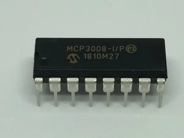
Now, what exactly is this rectangular black component with 16 pins?
To comprehend the connection between the MCP3008 pins and our Raspberry Pi, let's refer to the pin reference.
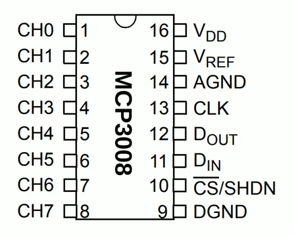
As depicted in the illustration above, the MCP3008 I/P chip has a semi-circle positioned at the top, with 8 pins on both the left and right sides.
The 8 pins on the left side correspond to the analog inputs that we intend to read using our Raspberry Pi. You will need to connect the analog output of the desired sensor to one of these pins.
The 8 pins on the right side are the ones we will connect to our Raspberry Pi:
– VDD (Pin 16) to the 3.3V pin on the Raspberry Pi
– VREF (Pin 15) to the 3.3V pin on the Raspberry Pi
– AGND (Pin 14) to the GND pin on the Raspberry Pi
– CLK (Pin 13) to Pin 23/SCLK on the Raspberry Pi
– DOUT (Pin 12) to Pin 21/MISO on the Raspberry Pi
– DIN (Pin 11) to Pin 19/MOSI on the Raspberry Pi
– CS (Pin 10) to Pin 24/CE0 on the Raspberry Pi
– DGND (Pin 9) to the GND on the Raspberry Pi
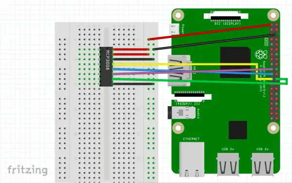
Considering these details, the following diagram illustrates how you can establish the connections between these 8 pins and your Raspberry Pi:
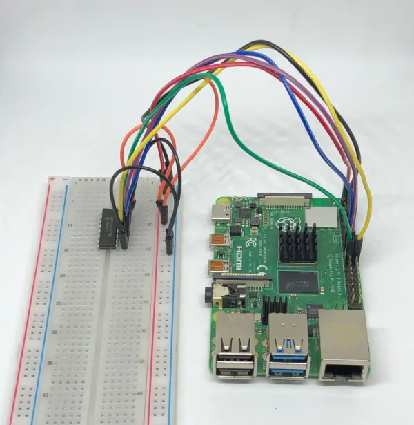
Once you have successfully established the connections between the MCP3008 I/P chip and your Raspberry Pi, your setup might resemble the following illustration:
Setting up Raspbian to run your Raspberry Pi
By now, you should have already configured a version of Raspbian to operate on your Raspberry Pi.
If you haven't completed this step yet, you can refer to one of the following articles for assistance:
– Guide on setting up Raspbian Buster Lite for Raspberry Pi server projects
– Tutorial on setting up Raspbian Buster for your Raspberry Pi 4 Model B
Enabling the SPI master driver with raspi-config
After successfully setting up Raspbian on your Raspberry Pi, you need to enable the SPI master driver using the `raspi-config` tool.
Enabling the SPI master driver will enable communication between your Raspberry Pi and the MCP3008 I/P chip.
Setting up a Python 3 virtual environment for reading analog inputs through the MCP3008 I/P chip
As a proponent of utilizing Python 3 virtual environments for running applications on a Raspberry Pi, I will now demonstrate how to set up the virtual environment for the Python 3 application that we will later execute.
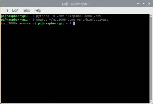
To begin, let's create the virtual environment using the following command:python3 -m venv ~/mcp3008-demo-venv
Once the command has completed, the Python 3 virtual environment will be located in the `~/mcp3008-demo-venv` directory.
Next, let's activate the virtual environment by executing the following command:source ~/mcp3008-demo-venv/bin/activate
With that in mind, we can proceed to install the necessary dependencies for our Python 3 application.
To read analog inputs through an MCP3008 I/P chip using Python 3, we can utilize Adafruit's CircuitPython library for MCP300x SPI ADC.
To install Adafruit's CircuitPython Library for MCP300x SPI ADC, execute the following command:pip install adafruit-circuitpython-mcp3xxx
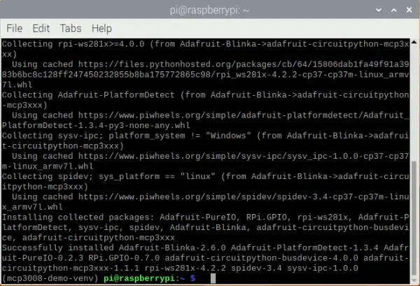
When the pip installation is successful, you will be able to read analog inputs from your Python 3 script inside that virtual environment.
Sample script to read raw ADC and ADC voltage from analog input connected to first channel of chip
Once we have set up the Python 3 virtual environment, let's explore how we can read from one of the analog inputs using Python.
For instance, if we intend to read the analog input connected to the first input channel (CH0) of the MCP3008 I/P pin, we can execute the following script:
|
1
2
3
4
5
6
7
8
9
10
11
12
13
14
15
16
17
18
19
20
21
22
23
|
import busioimport digitalioimport boardimport timeimport adafruit_mcp3xxx.mcp3008 as MCPfrom adafruit_mcp3xxx.analog_in import AnalogIn# create the spi busspi = busio.SPI(clock=board.SCK, MISO=board.MISO, MOSI=board.MOSI)# create the cs (chip select)cs = digitalio.DigitalInOut(board.CE0)# create the mcp objectmcp = MCP.MCP3008(spi, cs)# create an analog input channel on pin 0chan = AnalogIn(mcp, MCP.P0)while True: print('Raw ADC Value: ', chan.value) print('ADC Voltage: ' + str(chan.voltage) + 'V') time.sleep(2) |
Upon executing this script, an MCP object is generated from the SPI bus, which is associated with the SCLK, MISO, MOSI, and CE0 pins of your Raspberry Pi. Subsequently, an analog input channel is established to facilitate the reading of the analog input channel connected to pin 0 of the MCP3008 chip.
Once the channel is configured, the script proceeds to read and display the Raw ADC value and ADC voltage detected at pin 0 every two seconds.
If you desire to read analog inputs connected to other pins on the MCP3008 chip, you can simply modify the second input parameter to AnalogIn accordingly.
For instance, if you intend to read from the analog input channel on pin 7, you would make the following adjustment:
|
1
|
chan = AnalogIn(mcp, MCP.P0) |
to
|
1
|
chan = AnalogIn(mcp, MCP.P7) |
When I run this script with an analog input connected to the MCP3008 I/P chip, I get the following output:
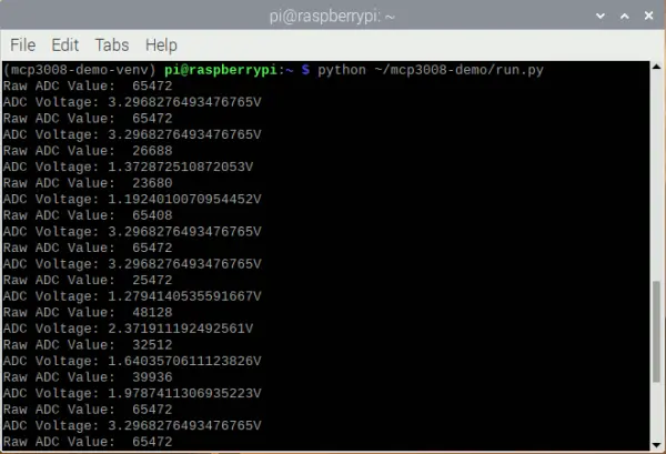
By now, you should be capable of utilizing this configuration to read a maximum of 8 analog inputs from your Raspberry Pi. Typically, an analog sensor will comprise at least three pins: + (positive), – (negative), and AO (analog output). You will connect the + pin to a 5V or 3.3V power source, the – pin to the ground, and the AO pin to one of the CH0 to CH7 pins on the MCP3008 chip: