
In the previous Raspberry Pi project, I demonstrated how to blink an LED using Raspberry Pi and Python programming. Continuing with the series, this project focuses on interfacing a 16×2 LCD with Raspberry Pi.
This project provides a comprehensive guide on the steps involved in interfacing a 16×2 LCD with Raspberry Pi. It covers essential aspects such as the circuit diagram, required components, the functioning of the LCD, the Python program, and an explanation of the code.
While the Raspberry Pi computer is capable of performing various tasks, it lacks a built-in display, which limits its usability in simple projects. However, by interfacing a 16×2 alphanumeric character LCD display with Raspberry Pi, you can conveniently present essential information.
The combination of Raspberry Pi and a 16×2 LCD display offers extensive possibilities for numerous projects and applications.
Before proceeding with the 16×2 LCD interfacing, it is important to understand how to set up the Raspberry Pi in a headless manner, without the need for a monitor and keyboard.
A Brief Note about 16×2 LCD
The 16×2 LCD display is widely recognized and favored by hobbyists, students, and electronics professionals alike. It is a popular choice due to its versatility and functionality. This display module consists of two rows, each capable of displaying up to 16 characters.
The majority of 16×2 LCD display modules available in the market are built upon the Hitachi HD44780 LCD Controller. This controller has become the standard for such displays, providing a reliable and consistent interface for various applications.
Typically, a 16×2 LCD Module consists of 16 Pins. The pin description of the 16×2 LCD Display Module is shown in the following table.
| Pin Number | Name | Function |
| 1 | Vss | GND |
| 2 | Vdd | +5V |
| 3 | Vo | Contrast adjust pin |
| 4 | RS | command register when 0; and data register when 1 |
| 5 | R/W | 0 to write; 1 to read |
| 6 | E | Sends data to data pins when a high lo low pulse is given |
| 7 | DB0 | Data pin |
| 8 | DB1 | Data pin |
| 9 | DB2 | Data pin |
| 10 | DB3 | Data pin |
| 11 | DB4 | Data pin |
| 12 | DB5 | Data pin |
| 13 | DB6 | Data pin |
| 14 | DB7 | Data pin |
| 15 | A | LED Backlight (+5V) |
| 16 | K | LED Backlight (GND) |
Circuit Diagram of 16×2 LCD Interfacing with Raspberry Pi
The provided table outlines the pin description for a 16×2 LCD, indicating the presence of 8 data pins. These data pins enable the configuration of the 16×2 LCD in two modes: 8-bit mode and 4-bit mode. In the following sections, I will present the circuit diagram for both modes.
Fritzing Circuit
When utilizing the 8-bit mode, all 8 data pins (D0 to D7) are utilized for data transfer. However, this mode requires a greater number of pins on the Raspberry Pi for connection. Consequently, we have chosen to utilize the 4-bit mode for the LCD. The circuit diagram below illustrates this configuration, featuring Fritzing parts.
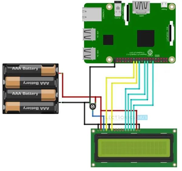
Circuit Diagram
The provided image depicts the wiring diagram for the showcased circuit of this project, specifically the LCD in 4-bit mode. In this mode, only 4 data pins, namely D4 to D7, of the LCD are utilized for data transmission and communication.
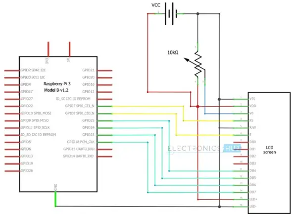
Please take note that for this project, we have utilized the 4-bit mode of the 16×2 LCD display. The Python code provided in the explanation is specifically tailored for this configuration. If you choose to configure the circuit in the 8-bit mode, slight modifications will be necessary in the Python program.
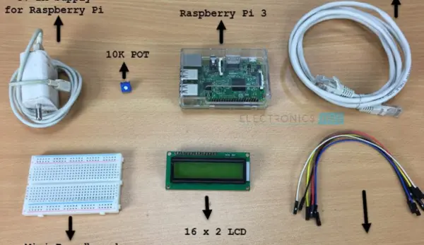
Components Required
- For this project, you will need the following components and materials:
- Raspberry Pi 3 Model B (or any Raspberry Pi model)
- 16×2 LCD Module
- 10 KΩ Potentiometer
- Mini Breadboard
- Connecting wires (Jumper wires)
- 5V – 2A Power Supply
- Miscellaneous items such as a computer, Ethernet cable, etc.
These are the necessary items to successfully complete the project.
Circuit Design
The circuit design for connecting a 16×2 LCD with Raspberry Pi is straightforward. Begin by connecting pins 1 and 16 of the LCD to the ground (GND), and connect pins 2 and 15 to a 5V power supply.
Next, connect a 10KΩ Potentiometer to pin 3 of the LCD, which is the contrast adjust pin. The three control pins of the LCD, namely RS (Pin 4), RW (Pin 5), and E (Pin 6), should be connected to GPIO Pin 7 (Physical Pin 26), GND, and GPIO Pin 8 (Physical Pin 24), respectively.
Please note that the Raspberry Pi Pin numbering is expressed using the BCM Numbering Scheme.
Now, let's focus on the data pins of the LCD. Since we are configuring the LCD in 4-bit mode, we only need to use four data pins (D4 to D7). Connect D4 of the LCD to GPIO25 (Physical Pin 22), D5 to GPIO24 (Physical Pin 18), D6 to GPIO23 (Physical Pin 16), and D7 to GPIO18 (Physical Pin 12).
Python Program for Interfacing 16×2 LCD with Raspberry Pi
| #!/usr/bin/env python | |
| import RPi.GPIO as GPIO | |
| from time import sleep | |
| # Define GPIO to LCD mapping | |
| LCD_RS = 7 | |
| LCD_E = 8 | |
| LCD_D4 = 25 | |
| LCD_D5 = 24 | |
| LCD_D6 = 23 | |
| LCD_D7 = 18 | |
| # Define some device constants | |
| LCD_WIDTH = 16 # Maximum characters per line | |
| LCD_CHR = True | |
| LCD_CMD = False | |
| LCD_LINE_1 = 0x80 # LCD RAM address for the 1st line | |
| LCD_LINE_2 = 0xC0 # LCD RAM address for the 2nd line | |
| # Timing constants | |
| E_PULSE = 0.0005 | |
| E_DELAY = 0.0005 | |
| def main(): | |
| # Main program block | |
| GPIO.setwarnings(False) | |
| GPIO.setmode(GPIO.BCM) # Use BCM GPIO numbers | |
| GPIO.setup(LCD_E, GPIO.OUT) # E | |
| GPIO.setup(LCD_RS, GPIO.OUT) # RS | |
| GPIO.setup(LCD_D4, GPIO.OUT) # DB4 | |
| GPIO.setup(LCD_D5, GPIO.OUT) # DB5 | |
| GPIO.setup(LCD_D6, GPIO.OUT) # DB6 | |
| GPIO.setup(LCD_D7, GPIO.OUT) # DB7 | |
| # Initialise display | |
| lcd_init() | |
| while True: | |
| # Send some test | |
| lcd_string(“Electronics Hub “,LCD_LINE_1) | |
| lcd_string(” Presents “,LCD_LINE_2) | |
| sleep(3) # 3 second delay | |
| # Send some text | |
| lcd_string(“Rasbperry Pi”,LCD_LINE_1) | |
| lcd_string(“16×2 LCD Test”,LCD_LINE_2) | |
| sleep(3) # 3 second delay | |
| # Send some text | |
| lcd_string(“1234567890*@$#%&”,LCD_LINE_1) | |
| lcd_string(“abcdefghijklmnop”,LCD_LINE_2) | |
| sleep(3) | |
| def lcd_init(): | |
| lcd_display(0x28,LCD_CMD) # Selecting 4 – bit mode with two rows | |
| lcd_display(0x0C,LCD_CMD) # Display On,Cursor Off, Blink Off | |
| lcd_display(0x01,LCD_CMD) # Clear display | |
| sleep(E_DELAY) | |
| def lcd_display(bits, mode): | |
| # Send byte to data pins | |
| # bits = data | |
| # mode = True for character | |
| # False for command | |
| GPIO.output(LCD_RS, mode) # RS | |
| # High bits | |
| GPIO.output(LCD_D4, False) | |
| GPIO.output(LCD_D5, False) | |
| GPIO.output(LCD_D6, False) | |
| GPIO.output(LCD_D7, False) | |
| if bits&0x10==0x10: | |
| GPIO.output(LCD_D4, True) | |
| if bits&0x20==0x20: | |
| GPIO.output(LCD_D5, True) | |
| if bits&0x40==0x40: | |
| GPIO.output(LCD_D6, True) | |
| if bits&0x80==0x80: | |
| GPIO.output(LCD_D7, True) | |
| # Toggle ‘Enable' pin | |
| lcd_toggle_enable() | |
| # Low bits | |
| GPIO.output(LCD_D4, False) | |
| GPIO.output(LCD_D5, False) | |
| GPIO.output(LCD_D6, False) | |
| GPIO.output(LCD_D7, False) | |
| if bits&0x01==0x01: | |
| GPIO.output(LCD_D4, True) | |
| if bits&0x02==0x02: | |
| GPIO.output(LCD_D5, True) | |
| if bits&0x04==0x04: | |
| GPIO.output(LCD_D6, True) | |
| if bits&0x08==0x08: | |
| GPIO.output(LCD_D7, True) | |
| # Toggle ‘Enable' pin | |
| lcd_toggle_enable() | |
| def lcd_toggle_enable(): | |
| # Toggle enable | |
| time.sleep(E_DELAY) | |
| GPIO.output(LCD_E, True) | |
| time.sleep(E_PULSE) | |
| GPIO.output(LCD_E, False) | |
| time.sleep(E_DELAY) | |
| def lcd_string(message,line): | |
| # Send string to display | |
| message = message.ljust(LCD_WIDTH,” “) | |
| lcd_display(line, LCD_CMD) | |
| for i in range(LCD_WIDTH): | |
| lcd_display(ord(message[i]),LCD_CHR) | |
| if __name__ == ‘__main__': | |
| try: | |
| main() | |
| except KeyboardInterrupt: | |
| pass | |
| finally: | |
| lcd_display(0x01, LCD_CMD) | |
| GPIO.cleanup() |
Working of the Project and Code Explanation
How to operate the Project?
The operation of the project involving the interfacing of a 16×2 LCD with Raspberry Pi is straightforward. Once you have made the necessary connections according to the circuit diagram, you can log in to your Raspberry Pi using an SSH client like Putty on Windows.
Alternatively, you can utilize any VNC Viewer software such as RealVNC (Please note that I have personally used RealVNC software to access the Raspberry Pi's desktop on my computer).
To proceed, create a folder named “Python_Progs” on the desktop of the Raspberry Pi. This is where you will save the Python program for interfacing the 16×2 LCD with Raspberry Pi. Use the “cd” commands in the terminal to navigate to this directory. Then, open an empty Python file named “lcdPi.py” by executing the following command in the terminal.
Please note that in the previous tutorial on how to blink an LED using Raspberry Pi, I have provided information about the Vim Editor.
Now, you need to copy the code provided above and paste it into the editor. Ensure that you use proper Tab characters to maintain the correct grouping of instructions in Python.
After saving the file, close the editor. To test the code, enter the following command in the terminal. If your connections and Python program are set up correctly, you should be able to see the text displayed on the 16×2 LCD.
To exit the program, simply press CRTL+C in the terminal.
Code Explanation
To begin with, I imported the GPIO package as GPIO (short for GPIO Package) and the sleep function from the time package. Following that, I assigned the GPIO pins for the LCD, including RS, E, D4, D5, D6, and D7. It's worth noting that I used the GPIO or BCM numbering scheme.
Please note that I also provided comments indicating the corresponding physical pin numbers for reference.
Subsequently, I utilized various functions from the GPIO package, such as GPIO.setwarnings(False), GPIO.setmode(GPIO.BCM), and GPIO.setup().
Finally, I implemented custom functions like lcd_init, lcd_string, lcd_display, and more. These functions allowed me to transmit the data from the Raspberry Pi to the 16×2 LCD Module for displaying the desired information.
Applications of Interfacing 16×2 LCD with Raspberry Pi
By connecting a 16×2 LCD to a Raspberry Pi, we can create a basic display option that allows us to show various information such as the date, time, status of a GPIO pin, and more. This integration provides a simple yet effective way to display essential data on the Raspberry Pi.
The applications for using a 16×2 LCD with a Raspberry Pi are diverse, ranging from straightforward projects like a weather station or temperature control system to more complex endeavors like robotic vehicles. Regardless of the specific application, having a compact 16×2 LCD display can greatly enhance the functionality and user experience of the Raspberry Pi.