
Hi Makers!
Intro
It's about time I shared this one with you all. This project has been going so long, you would not believe. I started this before our Hack Space existed [2011 ish?], and has continued to be in a transient ‘not finished, might finish, needs improvement' state forever. This Instructable will hopefully inspire you to go and do something similar with your own take on what this idea aims to accomplish and/or solve.
Objective
I intended to make a cheap/custom version of a Managed PDU that would monitor your internet connection, and power-cycle your modem/router/gateway device on the assumption that it had crashed, and “turning it off and on again” [the network engineer's favourite cop-out/easy fix!] would fix all that.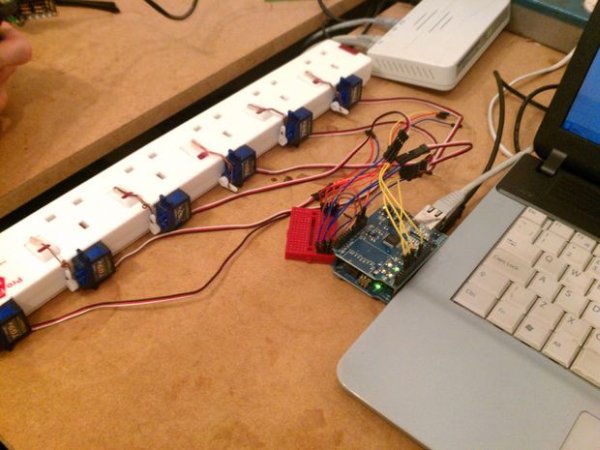
History
This project started life as a concept plus a few hastily-bought bits, and the idea was demonstrated at a Bar Camp many years ago in my current home town of Newcastle upon Tyne in England. Since starting the project, I have had the device on show at several Maker Faires and Tech Events of a similar nature, but the servos were simply set to randomly turn on-and-off often enough to impart how the mechanical aspect worked.
Why Servos?
A lot of people have wondered why I chose to use Servos linked to switches instead of, maybe, perhaps, Solid State Relays or something similar. The reason for this is quite simple: Accessibility and safety. This solution means that no-one needs to mess directly with dangerous 240v mains electricity, so it widens the base of Makers that would be able to take on this project, or something similar. It also means you have a neat row of sockets to plug everything in, no messing with double-gang space-wasting sockets. 😀
Right, with all that lengthy pre-able out of the way, better get cracking with the project documentation…
Step 1: Gather you Materials
These are the minimal items you'll need to complete this project:
- 6x 9g Servos
- 1x 6-Way Individually Switched Extension Lead
- Copper Wire
(I think I got mine from a 240v 5A solid-core lighting cable) - Hot Glue
- Small Breadboard
- 1x Arduino
(or compatible) - 1x Arduino Ethernet Shield
- 1x Raspberry Pi
- 1x SD Card
- USB A to USB B lead
- Micro USB lead
- Ethernet cable
(the sort typically used with printers) - Male-Male jumper wires
- Female-Female jumper wires
- 5v PSU with USB Port [a.k.a. USB Charger]
(minimum 1 amp) - Red single-core breadboard wire
- Black single-core breadboard wire
Step 2: Gather your Tools
The minimum tools you'll need to complete this project are:
- Wire strippers
- Small wire snips
- Needle nose pliers
- Soldering iron
- Glue gun
- Sand paper
- Sharpie/small permanent marker
- Drill
- Drill bit (to fit the copper wire diameter)
- Windows (Vista/7/8/8.1/10) Computer
Step 3: Prep the Servos
So that the servos will stick to the 6-way better with the hot glue…
- Check the position of the servo against the 6-way
- Remove the label from the side that will be glued to the 6-way
- Roughen-up the smooth plastic surface of the servo body with sandpaper
(I actually used a Jeweler's Screwdriver…) - Roughen-up the smooth plastic surface of the 6-way
(Mine was already a matte/rough finish)
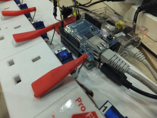
Step 4: Position and fix the servos
- Hold the servo in position on the 6-way
(This should be in line with the switch) - Mark the position of the servo with a sharpie or small permanent marker
- Hot glue the servo in place
- Repeat for the other five servos
Step 5: Copper linkage
This step really does require patience, skill, dexterity…and time…
NOTE: If you prefer 3D printed levers, see the ‘3D printed levers' step.
- Cut a length of copper for the switch lever
- Roughly double the length and add a bit extra to accommodate the hoop/eye
(Have a look at the pictures above for guidance)
- Roughly double the length and add a bit extra to accommodate the hoop/eye
- Bend the lever to shape
- Position the lever on the switch to check for good fit between switch and servo
- Repeat steps 2 & 3 if necessary!
- Cut a length of copper for the link arm
- Add extra to accommodate the hoop/eye at each end
(Have a look at the pictures above for guidance)
- Add extra to accommodate the hoop/eye at each end
- Bend the link arm to shape
- Repeat steps 5 & 6 if necessary!!
- Check and mark the position of the link on the servo arm
- Drill the arm hole out a bit bigger if necessary
- Link all the bits together
- Hot-melt glue the lever onto the switch
(Use a bit of electrician's/masking/whatever suitable tape to hold things in place)
Step 6: 3D printed levers
If, instead of the copper-wire levers, you would like 3D printed levers, follow these instructions. It may be good to refer back to the ‘Copper linkage' instructions that detail how to create the copper levers, as there is a bit more detail about how to correctly size and position the linkages.
- Download the STL
- Open in your favourite slicing software
- Slice it for your printer
- Print out six of them
- You may need to drill out the holes to properly accommodate the copper link wires
- Make some new linkages out of copper wire
(If you previously made the other linkages, they won't fit – you may benefit from reading the ‘Copper linkage' step about correctly sizing the copper wire linkages.) - Glue the levers to the switches
- Switch the switches to the ‘on' position
- Move the servo arms to the ‘on' position
- Remove the servo arms
(First, you'll need to remove a screw from the servo shaft) - Hook the linkages into the servo arm and the lever holes
- Re-attach the servo arms

Step 7: Test your servos
It will be fine for you to test that all your servos adequately operate the switches, if you hook them up one-by-one.
[Typical] Servo wire colour guide
These 9g servos normally have three wires that come from the motor housing and terminate in a 3-pin female header/connector. The wire colour key is typically as follows:
- White/Yellow: Signal
(The signal is a PWM frequency – you can find out more here) - Red: +5v/Vcc
- Black: Ground/GND
NOTE: If you want to be 100% certain, please check the manufacturer's specification/technical sheet for your servo model.
Connect a servo
The following connections will work for the example ‘servo sweep' sketch:
- White/Yellow >> PWM pin 9
- Red >> 5v power pin
- Black >> GND power pin
Upload a test sketch
The test sketch you can use is on the Arduino.cc site:
https://www.arduino.cc/en/Tutorial/Sweep
Observe
Keep an eye on the servo as it sweeps through its full rotation. The cheap 9g servos seem not to be very accurate, and don't seem to correctly sweep a full 180 degrees. YMMV! Watch out for the servo ‘binding', where it gets jammed by a limitation in the mechanics of your linkage and lever setup. If it binds, you may want to modify the minimum/maximum angles for the servo.
For more detail: Internet of Things (IoT) Extension Lead