Indeed, the Raspberry Pi Computer is a compact PC that is approximately the size of a credit card and comes at an affordable price of $35. These tiny nano PCs offer countless possibilities and applications. People have transformed them into personal video recorders (PVRs), retro gaming machines, weather stations, in-car computers, jukeboxes, and numerous other innovative ideas. When I embarked on this project four weeks ago, my initial goal was to determine the feasibility of creating an ultra-portable, mobile Raspberry Pi that could be taken on the go. During the construction of my Pi-to-Go device, I constantly found myself envisioning additional features that would enhance its capabilities, and I diligently worked to bring those ideas to life.
With the successful completion of my mobile Raspberry Pi Computer, I am excited to share every detail of this open-source project with you. I aim to provide comprehensive guidance on how to build your own device, including links to the required parts for purchase and the STL files for 3D printing your own case. So, let's dive right in and get started!
Allow me to provide a brief introduction about myself. I am the founder and CEO of Parts-People.com, Inc., a company dedicated to dealing exclusively with Dell Laptops. Our expertise lies in Dell laptop repair, refurbishment, and the supply of Dell replacement parts. With over a decade of experience in repairing and assembling laptops, I bring a wealth of knowledge to this project. Now, let's proceed to the next topic.
LCD Screen
For the display of my mobile Raspberry Pi project, I opted for an aftermarket backup camera system LCD that is typically installed in cars. Although the screen has a low resolution, I plan to explore better upgrades for future iterations of the mobile RPi to-go. However, for this initial proof of concept, the screen functions adequately. It measures 3.5 inches and has a 4:3 aspect ratio. The display utilizes a composite input and is capable of presenting a resolution of 640 x 480 pixels.
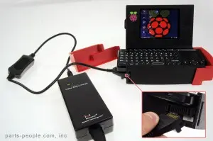
Battery Pack
Before we proceed, I must emphasize the importance of exercising extreme caution when working with lithium-ion batteries. Neither Parts-People.com, Inc. nor I can be held responsible for any damages or issues that may arise from following this tutorial. Please proceed at your own risk. Given that my company specializes in laptop parts, it was natural for me to utilize a laptop battery for this project. However, laptop batteries are not designed for direct usage as a battery pack without proper considerations. I knew it was feasible, but I needed to determine the most effective and safest approach for extracting power from the battery and recharging it. In this case, I utilized a Dell Latitude D600 laptop battery by removing it from its original case. The battery happened to be the appropriate size, had the correct voltage, and I had an ample supply of them. These batteries come with a standard Dell 9-pin battery connector. To extract power from this battery, you will need to connect pins 1, 2, and 4 together for the negative/ground (-) connection, and pins 8 and 9 together for the positive (+) connection. It is crucial to ensure that the leads are connected correctly. Please refer to the provided picture for the pinouts.
Charging the battery was a straightforward process. I simply acquired an aftermarket laptop battery charger that directly connects to the battery's 9-pin connector. The charger I purchased also includes a built-in battery level indicator, which makes monitoring the charging progress convenient.
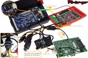
Internal Powered Hub
A significant challenge with the Raspberry Pi is its limited power supply capability. The RPi relies on a micro USB 5V power source, with a recommended minimum of 750mA, although 1A is preferable. However, the issue lies in the fact that the USB ports themselves can only deliver around 120mA per port, which is insufficient to power many peripherals. To overcome this hurdle, I discovered a remarkably compact 7-port USB hub that could be externally powered. After disassembling the hub, I identified the need to power five devices: a wireless WiFi dongle, a Bluetooth dongle, an SSD hard drive, a keyboard/mouse transmitter, and the Raspberry Pi itself. The battery pack I used supplied 11.1 volts, while the USB hub required 5 volts. To bridge this gap, I connected the battery to the LCD screen, which accepted an input of 9V to 13V. I knew that the LCD screen would contain components that required a 5V power source, such as the LED LCD backlight. By locating the onboard voltage regulator and carefully soldering leads across the 5V capacitor, I was able to connect them to the 5V input on the powered USB hub. This ingenious solution provided clean and regulated power for all of our devices, ensuring their optimal functionality.
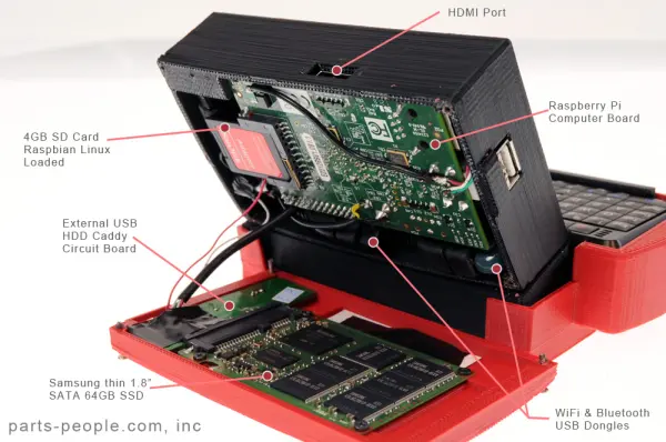
Extended Storage
Indeed, I did include a 64GB SSD (Solid State Drive) in my setup. The rationale behind this choice was to address the limited RAM capacity of the Raspberry Pi. The model B version 1 has only 256MB of RAM, while the model B version 2 has 512MB. To mitigate this limitation, I needed a solution that wouldn't strain the SD card with excessive read/write operations, as SD cards have a finite lifespan and tend to be slower. Consequently, I opted for a 64GB Sata II SSD manufactured by Samsung (specifically, model # MMBRE64GHDXP). Since I had several of these SSDs readily available, it made for a convenient choice. To connect the SSD directly to the internal power USB hub, I utilized the circuit board of an external USB hard drive caddy. With the setup complete, I configured a 1GB (1,024MB) Linux swap partition to compensate for the lack of RAM, while the remaining space was formatted in ext4 for extended storage purposes.
Built-in WiFi & Bluetooth
To maximize the functionality of the mobile Pi, I decided to incorporate several additional features. This included integrating a nano USB WiFi dongle and a nano USB Bluetooth dongle directly into the setup. To ensure seamless integration, I soldered these dongles directly to the built-in powered USB hub.
Operating System
For my setup, I opted to use the stock Raspbian Linux distribution available for download from raspberrypi.org. While using this Linux distribution, I made a few modifications to enhance its performance. Firstly, I tweaked the config.txt file to ensure proper display settings for the LCD screen, allowing it to fill the entire screen area. Additionally, I added a 1GB Linux swap partition to address any potential memory limitations. Other than these adjustments, I kept the Raspbian Linux installation largely unchanged.
overscan_right=-40
overscan_top=-30
overscan_bottom=-30
sdtv_mode=2
Keyboard & Touchpad Mouse
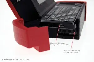
I acquired a wireless 2.4GHz USB keyboard and mouse combo for my setup. Although I would have preferred a wired USB option, the wireless combo was the ideal size and offered a suitable price point. To facilitate easy access and storage, I designed the setup with an access door on the left side. This door allows the keyboard to slide in and out conveniently. Furthermore, the access door also provides access to the on/off switch and mini USB charge port for the keyboard.
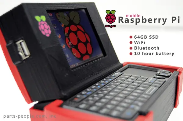
Overall Specs
The Raspberry Pi board I am using is a model B (revision 1) but you can use the model B (version 2) for this build.
| CPU | Broadcom BCM2835 ARM11 700Mhz |
| Memory | 256MB (shared with GPU) |
| Main Storage | 4GB SD Card (OS Installed) |
| Extended Storage | 64GB Sata II SSD (1GB linux swap) |
| WiFi Wireless | Built-in B/G/N Card |
| Bluetooth | Built-in Bluetooth 3.0 |
| Peripherals | 1 Powered USB Port |
| Video Output | HDMI Port |
| Keyboard / Mouse | QWERTY Keyboard with Touchpad Mouse |
| Weight | 1.65 lbs. |
3D Printed Case
With the help of Google SketchUp, my 3D printer, and a touch of creativity, I successfully designed a custom case for the mobile Pi-to-Go. The case consists of five individual parts, all of which are available for download on thingiverse.com. Each part is designed to securely snap together, except for the back access door, which is held in place by four screws.
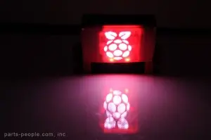
One distinctive feature of the case is the Raspberry Pi logo cutout on the back. To add an extra touch, I incorporated backlighting behind the logo. To achieve this effect, I utilized a backlight LED and repurposed an acrylic strip from the back of a backlit laptop keyboard. After shaping the strip to fit behind the Raspberry Pi logo, I soldered leads to connect it to a 5V power source. While this additional feature was not essential, I felt it added a nice touch to the overall design.
Where to buy the parts
As promised I will provide links to purchase all parts needed and I have already provided the links to download the 3D printer files (STL) above.
-
- LCD Screen – bought on amazon for $17.95 – here
-
- Raspberry Pi – bought on Newark/Element14 for $35 – here
-
- Mini Keyboard/Mouse – bought on amazon for $29.95 – here
-
- Standalone Battery Charger- bought on amazon for $75.00 – here
-
- Powered 7 Port USB Hub – bought on Parts-People.com for $14.95 – here
-
- 64GB SSD Hard Drive – bought on Parts-People.com for $69.95 – here
- Dell D600 Battery – bought on Parts-People.com for $88.50 – here
Schematic