I used to do many projects like this as a teenager, an eternity ago as it seems. One thing I learned the hard way is to always, always, assemble projects gradually, starting with the power. If the power is wrong, in the best case, you get really befuddled about what is going on, and in the worst case, you have to reorder every single part you just fried. (May include yourself ;-)) And reassemble everything while being angry. With the infernal stinkage of exploding electrolytic capacitors in between.
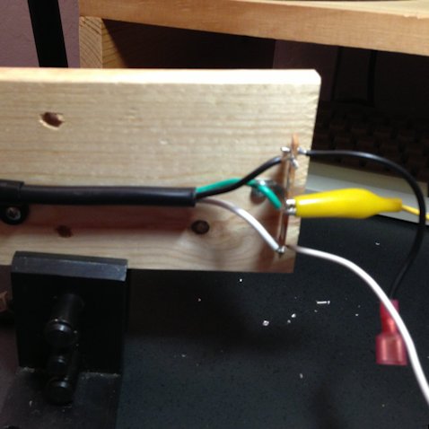
For this reason, I have this rather effective, but highly unorthodox “access to the power outlet” contraption. It’s basically an old power chord, with access to the wires, so I can quickly clip on whatever needs power.
Yes, it comes with a big sign for the family: “Touch nothing”. So far, nobody has.
Ok, so I smash the enclosure of the power supply that I ordered, unsolder the IEC C13 connector from the board, solder on some wires, connect them to the contraption, and measure: a bit more than 5V and a bit more than 12V with common ground. Great!
Next is connecting it to the Raspberry Pi. I cut the micro-USB chord, identify which wire is which, and solder the black and red strands to the power board. (Obviously after having disconnected the contraption from the outlet.) I plug the micro-USB connector in to the Raspberry Pi, plug in the contraption, and voila, the Raspberry Pi boots! Because it is already set up, I can ssh into it.
Now to the MOSFET stage that will convert 3.3V signals from the Raspberry Pi board to the 12V/125mA that the relays need. Here’s the circuit that I’m using (with apologies for the schematic, it’s the best I could do with OmniGraffle):
For more detail: My Raspberry Pi Pool Timer — Electronic Assembly


