Introduction
This is the follow-up article to the one published last week, which focused on the technical aspects and operational details of PIR motion sensors (read it here). In this article, we will delve into the practical applications of PIR motion sensors, specifically in conjunction with a Raspberry Pi board (in my case, a Raspberry Pi Model B+).
Connetting PIR with Arduino
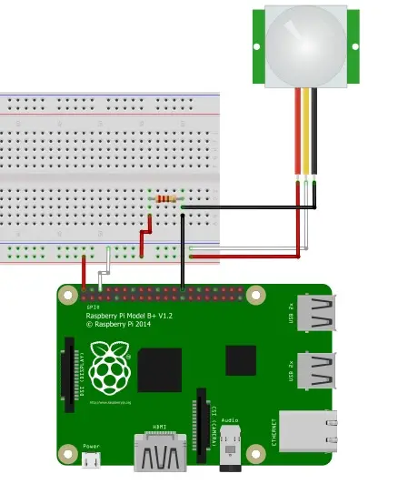
You will now resume from where the previous article left off, starting with the connection diagram created using Fritzing software. However, this time, the diagram will feature a Raspberry Pi instead of an Arduino. Therefore, you will need to construct a circuit based on the provided sketch, which includes the necessary connections for the Raspberry Pi.
In the previous article, you learned that the color, function, and arrangement of the three output cables may vary depending on the specific model of the PIR sensor. Therefore, it is crucial to consult the datasheet of the PIR model you possess before making any connections.
In the provided sketch, I have illustrated the connections based on my PIR model, the SE-10. If you have a different model, especially with cable arrangement, you should modify the connections accordingly. The red wire represents the +5V power supply, the white wire corresponds to the ground (GND), and the black wire carries the detection signal (ALM) from the sensor. Additionally, you may notice a 1kΩ resistor in the sketch.
To establish the correct connections between the PIR sensor and the GPIO pins, you will need a breadboard. Let's start with the PIR sensor and consider the colors of the three wires:
– Connect the red wire to the positive rail (+) of the breadboard.
– Connect the white wire to the negative rail (-) of the breadboard.
– Connect the black wire to an empty rail in the middle of the breadboard.
Next, you will need three more jumper wires, preferably in matching colors:
– Use a white jumper wire to connect the negative rail (-) to the GPIO GND (pin 6) of the Raspberry Pi.
– Use a red jumper wire to connect the positive rail (+) to the GPIO 5V (pin 2) of the Raspberry Pi.
– Use a black jumper wire to connect the central rail (the rail with the black wire) to the GPIO 7 (pin 26).
Insert a 1kΩ resistor into the breadboard in a way that connects the rail with the two black wires to a new empty rail. Finally, connect this empty rail to the positive rail (5V) using another red jumper wire.
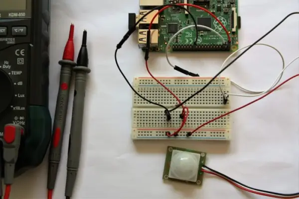
If you have followed all the steps correctly, your circuit should resemble the Frizing sketch. In my case, I have constructed a circuit as depicted in the following picture…
First example: print a message when a motions is detected.
Now that you have completed the connections, you can proceed with developing the Python code. The code will begin by activating the PIR sensor connected to the Raspberry Pi. It will then send a signal whenever it detects movement through the ALM wire.
To begin, set the GPIO pin 7 as an input and read the voltage (state) of this pin during the program execution. There are two possible states: LOW or HIGH. The HIGH state (3.3V) indicates that the PIR sensor has not detected any motion, while the LOW state (0V) indicates that motion has been detected.
As an initial example, you can write a simple script that displays a message in the terminal when motion is detected or not. Open a text editor and start entering the code. For instance, you can name the file pir01.py.
$ nano pir01.py
To begin, import the required Python library for working with GPIO, which is called RPi.GPIO. Also, import the time module, as it will be useful in the code for setting the delay between readings. Finally, set the numbering mode for the GPIO pins.
import RPi.GPIO as GPIO
import time

GPIO.setmode(GPIO.BCM)
Now, the next step is setting the GPIO 7 pin as input (this pin reads the HIGH and LOW state sent by the PIR sensor).
pirPin = 7
GPIO.setup(pirPin, GPIO.IN)
Before, it has been told that a you need to continuously read the status of the ALM wire, so you need to put the reading within a loop.
while True:
    if GPIO.input(pirPin) == GPIO.LOW
         print "Motion detected!"
    else:
         print "No motion"
    time.sleep(0.2)
When the ALM status is LOW, the condition is met, and a “motion detected” message will be printed in the terminal. On the other hand, if the state is HIGH, the condition is not met, and a “no motion” message will be printed instead.
This forms the core of the program. In more complex scenarios, such as home experiments, you would need to include an action as a response to motion detection within the if condition. For example, you could take a picture of the room where motion has been detected.
The complete code should resemble the following listing. Additionally, I have added a try-except construct to gracefully handle program termination when you press CTRL+Z. This ensures that the pin status is reset before quitting.
import RPi.GPIO as GPIO
import time

GPIO.setmode(GPIO.BCM)
pirPin = 7
GPIO.setup(pirPin, GPIO.IN)

try:
    while True:
        if GPIO.input(pirPin) == GPIO.LOW:
            print "Motion Detected!"
        else:
            print "No motion"
        time.sleep(0.2)
except KeyboardInterrupt:
    GPIO.cleanup()
This code allows you to perform the desired action or print messages based on the motion detection status. It also ensures a clean exit from the program and resets the pin status before quitting.
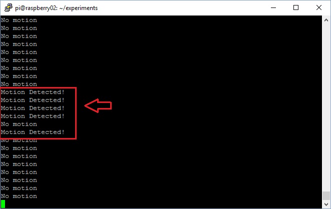
Once you have entered the code, save the program in nano (CTRL+O) and then quit (CTRL+X). Then, through a SSH session, run the program with
$ sudo python pir01.py
The program will continuously print the message “No motion”. However, whenever you move your head or place a hand near the PIR sensor, the program will print the message “Motion detected!”. This behavior will be repeated each time motion is detected by the sensor.