
A spinning top with a string is a traditional toy in Japan that is popular among children.
My daughter started practicing spinning tops at the nursery school.
I came up with an idea to add new feature to this top.
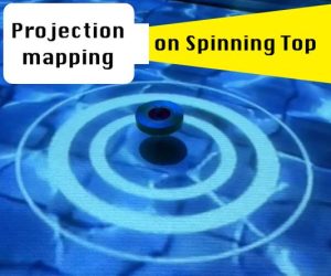
If the effect is projected to the spinning tops, it must be fun!
Supplies
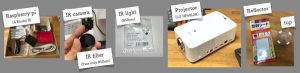
Materials:
- Raspberry pi (I use ver4)
- IR camera (Raspberry Pi PiNoir camera module V2.1)
- IR filter (There are several filter available for camera. I use 850nm type)
- IR light (LED, wavelength=850nm)
- Projector (Any, prefer to use LED projector)
- Top
- Reflector
Tools: 3D CAD, 3D printer, Solder
Step 1: How to Detect the Spinning Top
The concept is to project an effect with projection mapping onto a spinning top.
Stick a mark around the top. Then, when it is rotating, the mark looks like a circle, and when it stops rotating, the mark becomes a point. By detecting this difference with the camera, I should be able to detect whether it is rotating and the position of the top.
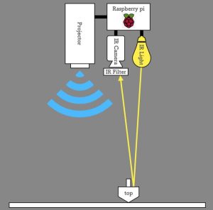
The image of the field is taken by a camera mounted on the ceiling and processed by Raspberry pi. Python is used for programming, and the OpenCV library is used.
Since the top is circular shape when viewed from above, camera will detect the circle shape even if it is stopped. It is difficult to detect only the mark on the top.
I came up with the idea of using an IR camera to detect only the marks. Install an infrared light next to the camera and install a filter that allows only infrared rays to pass in front of the lens.
Reflector is used as mark on top, you can detect only the mark without seeing the outer shape of the top from the camera.
Step 2: Design IR Light
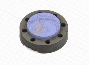
Design housing for the Camera-Light-Filter with 3D CAD (Fusion360). Print the model with 3D printer(Prusa mini) then assemble it.I use 8each of the IR LED that is for 850nm wavelength. I found IR filter in Amazon that is for camera mount. Smallest (and cheap) one was selected.
Make a draft program and test it on desk top.
OK, it looks working good!
Attached program is the finalized one.
Step 4: Projector Assembly
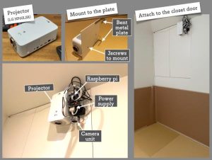
Prepare projector for projection mapping.
Mount the projector to the wall.
Secure the projector to the board with screws (Most of projectors have screw holes for hanging on the ceiling). Attach a bent metal plate to the back of the plate to hook. Please fix the projector firmly so that it will not fall.
Secure the IR camera, raspberry pi and power supply next to the projector.
Attach the projector to the wall.
Step 5: Adjust the Screen Size
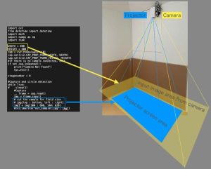
There is gap between Projector screen area and Camera area.
Projector screen size is depends on the projector type and distance to the floor. So need to adjust the screen size that fit to camera input. Project the effect to floor then see how the image is shifted from actual.
In the program, you can crop unnecessary area from camera input image.
To make full screen of the effect image, there are 2 option.
First is to make the program to be able to full screen. But, from my experience, this way makes processing speed very slow.
Second option is to use projector's function. Most of projector have a function that zoom the part of screen area. By using this function, zoom the effect window then you can show pseudo full screen. This way doesn't effect to the processing speed.