
These days, Closed-Circuit Television (CCTV) systems have gained popularity due to their effectiveness in providing peace and security to users. However, these systems have drawbacks such as unclear images and high storage requirements. In contrast, using the Raspberry Pi camera pinout with the circuit offers a better alternative by implementing the Motion Detection algorithm. This device helps save costs and reduces storage usage, while also supporting live streaming and motion detection.
To access remote features and utilize additional camera functions like image processing, a Raspberry Pi camera pinout is required. However, connecting a camera to a USB port on a PC differs from the process involved in using a Raspberry Pi camera pinout. In this regard, we will provide an overview of its features, guide you on its usage, and offer further insights.
Raspberry Pi Camera Interface
There are two main types of Raspberry Pi CSI camera connectors: the 15-pin connector and the 22-pin connector. These connectors provide the interface for connecting the camera module to the Raspberry Pi board.
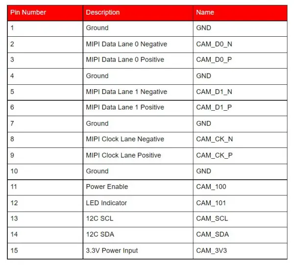
The 15-Pin Connector
The 15-pin connector is widely used and can be found on the Pi camera as well as the A and B series of standard Raspberry Pi models. Additionally, there are approximately three different 15-pin connectors used in Pi camera hardware.
The 15-pin connector has a pin pitch diameter of 1mm and supports a 2-lane MIPI interface.
Here is a summarized table describing the signals and camera board associated with this connector:
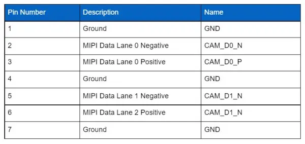
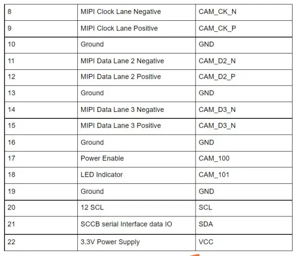
The 22-Pin Connector
In contrast, the 22-pin connector is utilized on devices such as the Compute Module IO Board and Raspberry Pi Zero-W.
The pin pitch diameter of this connector is 0.5mm, which is specifically suitable for the Compute Module IO Board. Additionally, it offers the capability of accommodating two additional MIPI data lanes, allowing the 22-pin connector to be expanded to a 4-lane configuration.
The following table provides a description of the signals and camera board associated with the 22-pin connector:
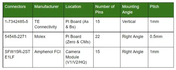
Raspberry Pi Camera Connector
The Raspberry Pi camera is equipped with three primary connectors: 54548-2271, SFW15R-2STE1LF, and 1-1734248-5.
The table below provides additional details about the connector, including its location, pitch, mounting angle, and other relevant information:
What Are the Features of a PiCam?
The PiCam possesses the following features:
– It incorporates an OmniVision 5647 Camera Module.
– It is compatible with the A & B models of the Raspberry Pi.
– The PiCam utilizes a MIPI Camera Serial Interface.
– The Raspberry Pi version of the PiCam is equipped with a 5MP color camera module, but it does not include a microphone.
– The resolution of the PiCam is 2592 x 1944 pixels.
– It is a portable device that supports only 3G connectivity.
– The PiCam supports various video resolutions, including 480p, 720p, and 1080p.
Are There Alternative Camera Modules for the Raspberry Pi?
Indeed, the answer is affirmative. There are several alternative camera modules available for Raspberry Pi, which encompass:
1. USB Camera
2. 5MP wide-angle camera with IR functionality
3. 8MP MIPI Camera
4. IR Night Vision Camera
How Do You Use the Camera module with Pi?
To ensure the proper handling of your Camera Module, it is important to take precautions against static electricity by grounding yourself with an earthed object such as a PC chassis. This helps prevent any potential damage to your device. Once you have taken this precaution, you can proceed with the installation of your Raspberry Pi Camera.
Begin by inserting the ribbon cable into the camera port, ensuring that the cable slots into the connector. The camera port is located between the micro-HDMI and USB ports on the Raspberry Pi board. The connector has silver connectors that should face towards the micro-HDMI ports.
If you are unsure about the correct orientation, make sure that the blue portion of the ribbon cable faces towards the Raspberry Pi's USB ports. Once the cable is properly connected, you can power on your Raspberry Pi by plugging it in.
Once your Raspberry Pi has booted up, you can access the terminal window to run commands and update your Raspberry Pi. To view the command options in the terminal window, navigate to the “interfacing options” using the navigation tool and press enter.
Upon selecting the “Camera” option in the terminal window, press enter to enable the camera command. Then, click on “Finish” and reboot your Raspberry Pi.
With the Camera Module successfully enabled, you can now utilize the “raspistill” command-line application to capture images in various formats such as JPEG or PNG. Additionally, you can capture videos using the “raspivid” command.
Applications
The Raspberry Pi Camera Module proves to be beneficial in various applications due to its support for data processing algorithms. It can be effectively utilized in the following domains:
1. Assisting in 3D vision-based tasks
2. Conducting vision inspection processes
3. Enabling automation in industrial settings
4. Enhancing augmented reality experiences
5. Supporting machine learning applications
6. Facilitating obstacle avoidance mechanisms
7. Conducting document scanning operations
8. Serving surveillance needs
9. Performing image processing tasks
10. Enabling head-mounted displays
11. Facilitating time-lapse video recording
12. Supporting robotics applications
In these areas, the Raspberry Pi Camera Module offers valuable functionalities and contributes to the successful implementation of various projects and tasks.