
Setting Up A Raspberry Pi Cluster
This guide provides step-by-step instructions for assembling and configuring a compact cluster of Raspberry Pi computers to create a parallel computing system. The instructions walk you through the process of connecting the computers, setting up the necessary environment, and verifying that everything functions properly.
Please note that these instructions are intended for users with some prior knowledge of computer concepts such as networks, command line usage, and file systems. While there are explanations provided within the document, a certain level of experience and a willingness to experiment are still required. These instructions may not be suitable for individuals who are completely new to working with computers.
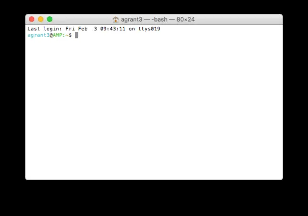
Command Terminals
In this document, the term “command terminals” will be used to refer to the means of accessing and configuring the Raspberry Pis, as well as issuing instructions to them. A command terminal provides users with a command line interface, allowing them to interact with the Raspberry Pis. Typically, a command terminal is represented by a screen displaying a prompt where commands can be entered. These prompts often have a similar appearance to the following examples:
At times, the command terminals may have a dark background with light text, but you can customize their appearance according to your preferences. It's important to note that a Raspberry Pi utilizes the Linux operating system, and its terminal functions and behaves in the same manner as described in this document.
If you are using a Windows system, you might need to install an SSH client in order to connect to the Raspberry Pi. One such free SSH client is PuTTY, which can be obtained from the provided link.
For Linux systems, you can open a command terminal on your computer by right-clicking and selecting “Terminal” or accessing it from the program menu.
On Windows, you will need to launch your SSH client.
If you are using a Mac OS machine, you can find Terminal under Utilities in the Applications folder.
Materials
Required
For this project, you will need the following equipment:
– 5 Raspberry Pis (Please note that the examples provided in these instructions use Raspberry Pi 3s. However, the instructions should be applicable to most Raspberry Pi models. If you encounter any issues, please submit an issue to Cluster Instructions).
– 5 Power Supplies or a single Multi-supply Unit.
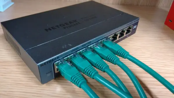
– 1 Switch with 8 Ports.
– 6 Ethernet Cables.
– 5 USB Cables.
– A laptop or desktop PC with a shareable ethernet connection.
Please keep in mind that the specifications mentioned above are specific to this project and can be modified based on your requirements and the availability of compatible hardware.
Optional
Suitable and Unsuitable Raspberry Pi Models
Please note that not all Raspberry Pi models are suitable for these instructions. The following models are considered suitable for this project:
– Raspberry Pi 3
– Raspberry Pi 2
On the other hand, the following Raspberry Pi models are unsuitable for these instructions as they either won't work or require significant changes and/or additional hardware:
– Raspberry Pi Zero
– Raspberry Pi Zero W
– Raspberry Pi Compute Module
It's important to verify the compatibility of your Raspberry Pi model before proceeding with these instructions to ensure that you have the appropriate hardware for a successful implementation.
Materials used in these instructions:
You will need the following components for this setup:
– 5 Raspberry Pi 3 units.
– 1 Multi-USB Power Socket. Please note that this particular model may no longer be available as it seems to have been discontinued.
– 1 Netgear GS108E Switch with 8 ports.
– 6 Ethernet Cables.
– 5 USB Cables with A-Type USB Male to B-Type Micro-USB Male connectors.
– 1 MacBook with a WiFi internet connection that can be shared via Ethernet.
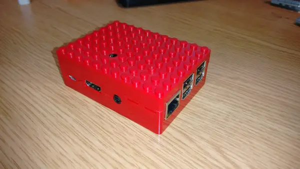
– 5 Raspberry Pi cases in a red Lego-style design.
Please ensure you have all these components ready before proceeding with the setup.
Important Note – Only for New Raspbian Installations
As a result of updates in recent versions of Raspbian and NOOBS distributions, there is a modification required for your Raspberry Pi SD Card before its initial boot.
The more recent versions of Raspbian come with SSH access disabled as the default setting. To proceed with the instructions provided below, you must re-enable SSH on your Raspberry Pi.
To achieve this, simply insert the microSD card containing Raspbian into your computer and create an empty text file named “SSH” in the boot partition. The boot partition is the disk that appears in your file system when you insert the microSD card.
After creating the “SSH” file, you will be able to boot Raspbian with SSH remote access enabled, allowing you to follow the instructions seamlessly.
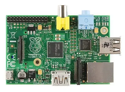
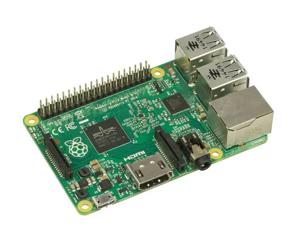
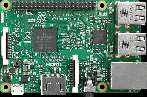
The Hardware
As of the time of writing, there are three different models of Raspberry Pi available in the market. To help differentiate between them, we have included the following images for reference:
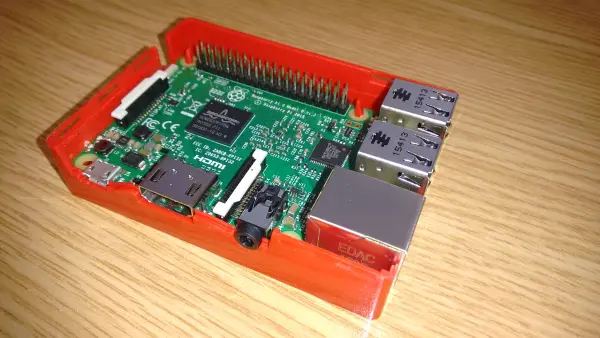
If you have chosen to use a case, this is the step where you would insert the Raspberry Pi into it. Here is an example of what a cased Raspberry Pi might look like:
Connecting the Raspberry Pi Cluster
Connect the Ethernet Cables to the ethernet ports:
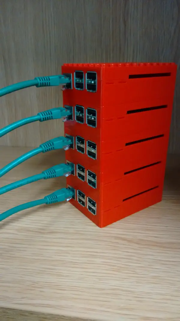
Connect the ethernet cables to the switch:
Now it should look something like:
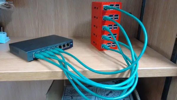
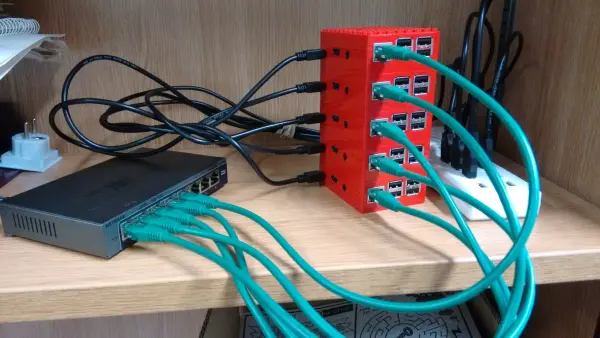
Establish a connection between your laptop or desktop computer and the switch by using an Ethernet cable. Please note that although the Raspberry Pi 3 has built-in wireless network capabilities, we will not be utilizing them in this setup, and it is likely that they have not been configured at this stage. With the network cables now connected, let's proceed to connect the power cables. Start by connecting the power cable to the switch.

Next, power on the switch by switching it on. After that, proceed to connect the micro USB end of the USB cables to each respective Raspberry Pi device.

Connect the other end of the USB cables to your power supply. In this scenario, we are utilizing an externally powered USB hub.

Now, plug in the power supply and switch it on. You should observe LED lights on or flashing for all the Raspberry Pi units. The overall setup should resemble something similar to this image:
With all the hardware connections in place, it's now time to begin configuring the software.
Network Software Setup
Note: The following instructions are based on the assumption that you are using a computer connected to a WiFi network and that the computer has an available Ethernet port to connect to the cluster.
For Mac OS users, follow these steps to configure internet sharing:
1. Open System Preferences on your laptop/desktop.
2. Select the “Sharing” option.
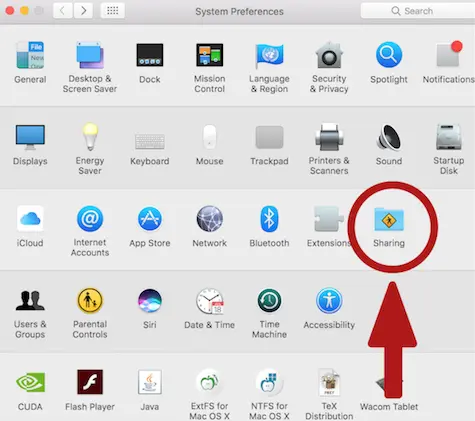
Click on the “Internet Sharing” option and select the option to share the connection from WiFi to Ethernet. This will activate a service that shares the internet connection from your WiFi network to the Raspberry Pis through the Ethernet connection provided by the switch.
Windows 10
Open the Settings menu on your computer, then select “Network and Internet” followed by “Network and Sharing Center.” From there, choose “Change Adapter Settings.” Look for the Wi-Fi connection (it may have a different name on your computer, but it should be indicated by a signal strength icon). Right-click on the Wi-Fi connection and select “Properties.”
In the properties window, go to the “Sharing” tab. Check the box that says “Allow other network users to connect through this computer's Internet Connection.” Make sure that the Home networking connection is set to your Ethernet network.
Now your internet connection is shared, but you will need to use Nmap to obtain the IP addresses of the Raspberry Pis. In the Network Connections window, locate the Ethernet connection (it should be listed there). Right-click on the Ethernet connection and choose “Properties.”
In the list labeled “This connection uses the following items,” click on “Internet Protocol Version 4.” Then, click on the “Properties” button that appears below the list. Take note of the IP Address and Subnet Mask listed.
You can now close the dialog boxes. To find the IP addresses of the Raspberry Pis, click on the following link: Windows IP Address Discovery. This will provide instructions on how to retrieve the IP addresses of the Raspberry Pis.
Linux TODO
Need to fill in
Getting into the Pi
To determine the IP addresses of your Raspberry Pis, follow these steps. Please note that the name of the shared network connection may be different on your computer. You can verify the name by running the “ifconfig” command before enabling sharing or connecting the adapter, and then running it again to observe any changes.
For macOS users, the shared network connection typically appears as an adapter named “Bridge100” after running the “ifconfig” command.
1. Open a command terminal on your macOS computer.
2. Type the “ifconfig” command to display the network interfaces.
3. Look for the interface named “Bridge100” or a similar name that corresponds to the Ethernet connection.
4. Take note of the IP address associated with the “Bridge100” interface. This IP address is most likely the one used for Ethernet.
By following these steps, you should be able to identify the IP address of the “Bridge100” interface or the relevant Ethernet interface on your macOS computer.

Type: ifconfig
This should put out something like:
lo0: flags=8049<UP,LOOPBACK,RUNNING,MULTICAST> mtu 16384
	options=3<RXCSUM,TXCSUM>
	inet6 ::1 prefixlen 128
	inet 127.0.0.1 netmask 0xff000000
	inet6 fe80::1%lo0 prefixlen 64 scopeid 0x1
	nd6 options=1<PERFORMNUD>
gif0: flags=8010<POINTOPOINT,MULTICAST> mtu 1280
stf0: flags=0<> mtu 1280
en0: flags=8863<UP,BROADCAST,SMART,RUNNING,SIMPLEX,MULTICAST> mtu 1500
	ether a4:5e:60:e7:21:0f
	inet6 fe80::a65e:60ff:fee7:210f%en0 prefixlen 64 scopeid 0x4
	inet 172.20.152.14 netmask 0xfffff000 broadcast 172.20.159.255
	nd6 options=1<PERFORMNUD>
	media: autoselect
	status: active
en1: flags=963<UP,BROADCAST,SMART,RUNNING,PROMISC,SIMPLEX> mtu 1500
	options=60<TSO4,TSO6>
	ether 6a:00:00:41:c6:f0
	media: autoselect <full-duplex>
	status: inactive
en2: flags=963<UP,BROADCAST,SMART,RUNNING,PROMISC,SIMPLEX> mtu 1500
	options=60<TSO4,TSO6>
	ether 6a:00:00:41:c6:f1
	media: autoselect <full-duplex>
	status: inactive
bridge0: flags=8822<BROADCAST,SMART,SIMPLEX,MULTICAST> mtu 1500
	options=63<RXCSUM,TXCSUM,TSO4,TSO6>
	ether a6:5e:60:7e:1d:00
	Configuration:
		id 0:0:0:0:0:0 priority 0 hellotime 0 fwddelay 0
		maxage 0 holdcnt 0 proto stp maxaddr 100 timeout 1200
		root id 0:0:0:0:0:0 priority 0 ifcost 0 port 0
		ipfilter disabled flags 0x2
	member: en1 flags=3<LEARNING,DISCOVER>
	        ifmaxaddr 0 port 5 priority 0 path cost 0
	member: en2 flags=3<LEARNING,DISCOVER>
	        ifmaxaddr 0 port 6 priority 0 path cost 0
	media: <unknown type>
	status: inactive
p2p0: flags=8843<UP,BROADCAST,RUNNING,SIMPLEX,MULTICAST> mtu 2304
	ether 06:5e:60:e7:21:0f
	media: autoselect
	status: inactive
awdl0: flags=8943<UP,BROADCAST,RUNNING,PROMISC,SIMPLEX,MULTICAST> mtu 1484
	ether ca:90:43:20:19:ba
	inet6 fe80::c890:43ff:fe20:19ba%awdl0 prefixlen 64 scopeid 0x9
	nd6 options=1<PERFORMNUD>
	media: autoselect
	status: active
vboxnet0: flags=8943<UP,BROADCAST,RUNNING,PROMISC,SIMPLEX,MULTICAST> mtu 1500
	ether 0a:00:27:00:00:00
	inet 192.168.59.3 netmask 0xffffff00 broadcast 192.168.59.255
vboxnet1: flags=8842<BROADCAST,RUNNING,SIMPLEX,MULTICAST> mtu 1500
	ether 0a:00:27:00:00:01
You are most likely to be looking for the bridge100 interface:
bridge100: flags=8863<UP,BROADCAST,SMART,RUNNING,SIMPLEX,MULTICAST> mtu 1500
	options=3<RXCSUM,TXCSUM>
	ether a6:5e:60:7e:1d:64
	inet 192.168.2.1 netmask 0xffffff00 broadcast 192.168.2.255
	inet6 fe80::a45e:60ff:fe7e:1d64%bridge100 prefixlen 64 scopeid 0xe
	Configuration:
		id 0:0:0:0:0:0 priority 0 hellotime 0 fwddelay 0
		maxage 0 holdcnt 0 proto stp maxaddr 100 timeout 1200
		root id 0:0:0:0:0:0 priority 0 ifcost 0 port 0
		ipfilter disabled flags 0x2
	member: en4 flags=3<LEARNING,DISCOVER>
	        ifmaxaddr 0 port 10 priority 0 path cost 0
	Address cache:
	nd6 options=1<PERFORMNUD>
	media: <unknown type >
	status: inactive
This is the IP address 192.168.2.1 (line beginning with inet above.)
There are two ways to find out what is connected: the first is to run the command arp.
arp -i bridge100 -a
This runs a program which returns information about what is connected currently to that interface. Command Breakdown:
 arp - program to run

-i value - use the interface value
-a - display all current connections
When you run this command you will get output which contains lines like:
? (239.255.255.250) at 1:0:5e:7f:ff:fa on bridge100 ifscope permanent [ethernet]
Running the arp program will give you a list of connected IP addresses on your Bridge100 interface, this list of addresses is the list of Raspberry Pi addresses – there should be the same number of addresses as you have Raspberry Pis connected.
The other way is to install a program like nmap, which is available from https://nmap.org/.
To run nmap to scan on your network you can do it in two ways:
- Scan a range of IP addresses:
nmap 192.168.2.1-255
Use this option if you know what range your connection sharing will use; replace the IP address range with your own values.
- Scan a subnet on the network:
nmap 192.168.2.0/24
Use this option if you only know the start of the IP address range (e.g. 192.168.2) and it will scan over the whole subnet.
Windows
If you are using Windows, it is recommended to install Nmap, which can be downloaded from the official website at https://nmap.org/. This is the simplest method to determine the IP addresses of the Raspberry Pis connected to your network.
After installing Nmap, open a command prompt and run the following command, replacing the IP address with the one you noted earlier when sharing the internet connection. However, modify the last number of the IP address to 0:
nmap -sn <IP_address>/24
For example, if your Ethernet IP address is 192.168.0.1, the command would be:
nmap -sn 192.168.0.0/24Executing this command will perform a network scan and display a list of active IP addresses within the specified range. These IP addresses correspond to the Raspberry Pis connected to your network.
c:\nmap 192.168.137.0/24
This should give output like:
C:\>nmap 192.168.137.0/24

Starting Nmap 7.40 ( https://nmap.org ) at 2017-04-26 15:53 GMT Daylight Time
Nmap scan report for 192.168.137.225
Host is up (0.00013s latency).
All 1000 scanned ports on 192.168.137.225 are closed
MAC Address: 98:5A:EB:C7:15:8B (Apple)

Nmap scan report for 192.168.137.1
Host is up (0.0013s latency).
Not shown: 997 closed ports
PORT    STATE SERVICE
135/tcp open  msrpc
139/tcp open  netbios-ssn
445/tcp open  microsoft-ds

Nmap done: 256 IP addresses (2 hosts up) scanned in 23.48 seconds
The Raspberry Pis connected to your network will appear as IP addresses in the Nmap scan report, excluding the one with the IP address you previously noted.
IP addresses are crucial for identifying and accessing the Raspberry Pis on the network. They serve as unique identifiers, similar to street addresses for physical locations. However, it's important to note that IP addresses can change over time. If you're interested in learning more about IP addresses and DHCP (Dynamic Host Configuration Protocol), you can find brief explanations at the following links:
– IP Addresses: [Link to resource explaining IP addresses]
– DHCP: [Link to resource explaining DHCP]
Now that the Raspberry Pis are powered on and we have determined their current IP addresses, it's time to proceed with configuration and setup. Please note that these IP addresses are only valid for the current connection to your computer. Once the setup is complete, the Raspberry Pis will be assigned new addresses by the cluster server.
192.168.2.18
192.168.2.19
192.168.2.20
192.168.2.21
192.168.2.22
I will designate the Raspberry Pi with the address 192.168.2.18 as the master node in the cluster, while the remaining Pis will act as worker nodes.
The master node is responsible for running the DHCP server to assign IP addresses, sharing its WiFi connection (if applicable), providing networked drive access for files, and initiating the execution of programs on the cluster.
On the other hand, the worker nodes will primarily handle the computation tasks within the programs we run on the cluster.
Setting Up the Main Node
Let's begin with the configuration of the master node.
Open your command terminal and enter the following command, replacing “192.168.2.18” with the IP address assigned to your Pi:
ssh [email protected]
You will get output like this coming up:
The authenticity of host '192.168.2.18 (192.168.2.18)' can't be established.
RSA key fingerprint is a0:97:1f:d6:df:8c:a5:45:db:fe:b4:94:46:1d:0f:48.
Are you sure you want to continue connecting (yes/no)?
Type yes in and the following will appear:
Warning: Permanently added '192.168.2.18' (RSA) to the list of known hosts.
[email protected]'s password:
Type in the password: raspberry
Now you have logged into your new master node for your cluster.
To breakdown what happened, you typed in
ssh [email protected]
This command initiates an SSH connection from your computer to the system with the IP address 192.168.2.18, using the username “pi.” SSH is a common method for remote system login, similar to accessing a supercomputer like ARCHER.
After executing the command, you will receive output similar to the following:
The programs included with the Debian GNU/Linux system are free software;
the exact distribution terms for each program are described in the
individual files in /usr/share/doc/*/copyright.

Debian GNU/Linux comes with ABSOLUTELY NO WARRANTY, to the extent
permitted by applicable law.
Last login: Fri Feb 26 03:25:51 2016
pi@raspberrypi:~ $
Let's do some main system configuration:
Type the command sudo raspi-config and press Enter/Return, e.g.:
pi@raspberrypi:~ $ sudo raspi-config
Running this command will launch a Raspberry Pi configuration program.
The use of “sudo” indicates that the subsequent commands will be executed as the super-user, granting permission to make system-level changes rather than just modifying user files.
When the menu appears:
1. Select option 3 for Boot Options.
2. Choose option B1 for Text console and press enter/return.
This configuration ensures that the Raspberry Pi boots to a command line interface instead of a graphical user interface (GUI) typically used in everyday computer usage.
Next, choose option 9 for Advanced Options.
Select option A2 for Hostname and press enter/return.
An information screen will appear—take the time to read it before proceeding.
On this screen, you will see the current hostname, which is an easily recognizable name for the Raspberry Pi you are currently logged into. To customize your cluster and make it more identifiable, you can choose a new name for the Raspberry Pi.
In my example, I will change the hostname to “beira” and confirm by pressing enter/return.
Next, we need to set the correct time zone to ensure accurate date and time on the Pi.
Select option 5 for Internationalisation Options.
Choose option T2 to change the timezone.
From the list, select your region (e.g., Europe).
Then choose the nearest location (e.g., London).
Once you're back in the main menu, use the cursor/arrow keys to navigate to the “Finish” button and press enter/return.
A prompt will ask if you want to reboot. Choose “yes” to reboot the Pi.
Your SSH session with the Raspberry Pi will end. The Raspberry Pi will take some time to reboot before you can log in again and continue. Please be patient during this process.
Now, log back into the Raspberry Pi using the previous SSH command and enter the password.
You will notice that the command line prompt displays “pi@your-hostname-here.” In my example, it shows:
pi@beira:~ $
We will now install some updates on the Raspberry Pi main software. The first command to run is rpi-update.
pi@beira:~ $ sudo rpi-update
This will update the Raspberry Pi with the latest version of the core software and firmware for the system – it will take a few minutes and start with output like:
 *** Raspberry Pi firmware updater by Hexxeh, enhanced by AndrewS and Dom
 *** Performing self-update
 *** Relaunching after update
 *** Raspberry Pi firmware updater by Hexxeh, enhanced by AndrewS and Dom
#############################################################
WARNING: This update bumps to rpi-4.9.y linux tree
Be aware there could be compatibility issues with some drivers
Discussion here:
https://www.raspberrypi.org/forums/viewtopic.php?f=29&t=167934
##############################################################
Would you like to proceed? (y/N)
If you do not want to perform this update, choose N, otherwise type y. You will need to reboot the Raspberry Pi for this to take effect.
pi@beira:~ $ sudo reboot
This process may take some time.
To summarize what we have accomplished so far:
1. We have connected the hardware and cables.
2. We have shared our internet connection.
3. We have chosen a master node and logged into it.
4. We have selected a hostname and updated the core software.
Now, log back into the node you are currently working on.
Before proceeding with any further software updates or installations, we will begin setting up the passwordless login system required for the cluster to run programs.
In the command line, execute the following command:
pi@beira:~ $ ssh-keygen -t rsa
Executing this command will generate a public/private key pair, which is a cryptographic system used for encryption and security to enable secure communication. The generation process will create a public file that can be shared with other machines or individuals you wish to communicate with, as well as a private file that must be kept confidential to ensure that only you can access the information sent to you or sent by you using your public key.
When prompted, you can use the default settings for the first prompt. For this cluster setup, it is recommended not to enter a passphrase (simply press the return/enter key when prompted for a passphrase). Your interaction with the command line should resemble the following:
pi@beira:~ $ ssh-keygen -t rsa
Generating public/private rsa key pair.
Enter file in which to save the key (/home/pi/.ssh/id_rsa):
Created directory '/home/pi/.ssh'.
Enter passphrase (empty for no passphrase):
Enter same passphrase again:
Your identification has been saved in /home/pi/.ssh/id_rsa.
Your public key has been saved in /home/pi/.ssh/id_rsa.pub.
The key fingerprint is:
9b:98:c7:86:17:0a:1e:32:95:65:ee:1c:0f:48:48:ef pi@beira
The key's randomart image is:
+---[RSA 2048]----+
| .... o          |
|  .o *           |
|    = +          |
|   o o +         |
|  o E o S        |
|   + o * +       |
|    . = B        |
|       +         |
|                 |
+-----------------+
pi@beira:~ $
Great! You have successfully set up an SSH key. Make sure to remember the process because you will need to repeat it later. Now, let's proceed with updating the operating system and installed software. Run the following command:
sudo apt-get update
This command will update the package lists and upgrade any installed packages to their latest versions. It may take some time to complete, so please be patient during the process.
This command retrieves information about the latest versions of packages available for the Raspberry Pi operating system. It usually takes around 30-50 seconds to complete. Now, let's proceed with the next command:
sudo apt-get upgrade
Running this command will upgrade the installed packages to their latest versions. Please note that the upgrade process may take some time, depending on the number and size of the packages being upgraded.
This command will upgrade the installed software to the latest versions, including bug fixes and improvements. When prompted, you should enter ‘Y' to proceed with the installation of the upgrades. The time required to complete this command depends on the number of upgrades being installed.
After the update process is finished, we will begin setting up the Network File System (NFS) server component. To start, we need to add a network module. Please run the following command:
sudo nano /etc/modules
This command installs the necessary packages for NFS server functionality.
This should open up a file like this:
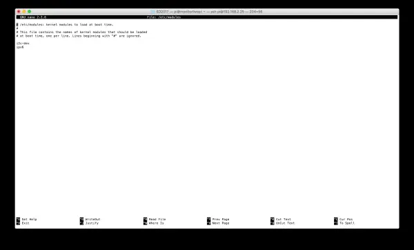
at the end of the file, using the cursor keys to move, if it is not present, add the following:
ipv6
- Now press the keys CRTL and O at the same time – this will save the file.
- Now press the keys CRTL and X at the same time – this will close nano.
Note: nano is a simple text editor program that we will be using during this configuration process.
Run the command:
sudo service rpcbind start
Now we will install the NFS Kernel server – this is needed to run the server for the NFS drive.
sudo apt-get install nfs-kernel-server
Now we will start to create the actual shared location. Start by creating a directory in /home for sharing
sudo mkdir -p /home/shared_dir
mkdir is a command used to create a directory (which can contain other directories and files).
Now change its access permissions so that everyone can read or write to this directory:
sudo chmod 777 /home/shared_dir
The “chmod” command is used to modify the access permissions of a file or directory. In this case, the command “chmod 777” is being used, which sets the permissions to allow everyone to read, write, and execute commands in that directory. If you only want the owner to have write permissions and others to have read permissions, you would use the permission set “644”. You can find more information about “chmod” in the Wikipedia entry for chmod.
Now, we need to mount the “shared_dir” and bind it.
sudo mount --bind /home/shared_dir/ /home/shared_dir/
This ensures that the system recognizes the directory as a mountable drive, allowing it to be shared with other computers.
Next, we need to ensure that the directory is mounted and exported every time the system boots up, and that other computers can access it.
Please run the following command:
sudo nano /etc/fstab
at the end of the file add the following:
/home/shared_dir /home/shared_dir none bind 0 0
- Now press the keys CRTL and O at the same time – this will save the file.
- Now press the keys CRTL and X at the same time – this will close nano.
To continue the configuration, run:
sudo nano /etc/default/nfs-kernel-server
Make sure that one of the following options is present in the opened file:
NEED_SVCGSSD=no
or
NEED_SVCGSSD=“no”
or
NEED_SVCGSSD=“”
or
NEED_SVCGSSD=
- Now press the keys CRTL and O at the same time – this will save the file.
- Now press the keys CRTL and X at the same time – this will close nano.
The configuration process continues with a mapping file, run:
sudo nano /etc/idmapd.conf
Ensure that under the [Mapping] section the following is present:
[Mapping]

Nobody-User = nobody
Nobody-Group = nogroup
Now run the following to expose the new directory to the network:
sudo nano /etc/exports
At the end of the file add the following to export your shared_dir to the network:
/home/shared_dir 192.168.2.0/24(rw,nohide,insecure,no_subtree_check,async)
This line will expose your shared_dir to the network where all the addresses start 192.168.2 and allow read and write acess.
As a final check on this we will examine the following files:
/etc/init.d/nfs-kernel-server
/etc/init.d/nfs-common
/etc/init.d/rpcbind
Have a look at each of the above files in nano. Each one, near the top of the file, should have a line:
# Default-Start: 2 3 4 5
however in some this may say:
# Default-Start: S
You need to change all the files that have an S to 2 3 4 5 and then run:
sudo update-rc.d -f rpcbind remove
sudo update-rc.d rpcbind defaults

sudo update-rc.d -f nfs-common remove
sudo update-rc.d nfs-common defaults

sudo update-rc.d -f nfs-kernel-server remove
sudo update-rc.d nfs-kernel-server defaults
If any of these commands fail with error messages, try the following:
sudo apt-get purge rpcbind
sudo apt-get install nfs-kernel-server
If any of the operations mentioned above failed, please try running the update command again.
Before we proceed with setting up a DHCP server, let's install MPI. MPI is a crucial technology used in parallel and high-performance computing, enabling processes to communicate in a standardized manner and collaborate to solve problems together in parallel. We will install MPI and test a simple program on a single node.
Please run the following command:
sudo apt-get install libxml2-dev
sudo apt-get install zlib1g zlib1g-dev
sudo apt-get install mpich
Now try running the command:
mpiexec —version
You should get output looking something like:
pi@beira:~ $ mpiexec --version
HYDRA build details:
    Version:                                 3.1
    Release Date:                            Thu Feb 20 11:41:13 CST 2014
    CC:                              gcc -D_FORTIFY_SOURCE=2 -g -O2 ...
    CXX:                             g++ -D_FORTIFY_SOURCE=2 -g -O2 ...
    F77:                             gfortran -g -O2 ...
    F90:                             gfortran -g -O2 ...
    Configure options:               ...
    Process Manager:                         pmi
    Launchers available:                     ssh rsh fork slurm ll ...
    Topology libraries available:            hwloc
    Resource management kernels available:   user slurm ll lsf sge pbs cobalt
    Checkpointing libraries available:       blcr
    Demux engines available:                 poll select
Please note that the output provided above has been shortened. When you run the command, you will see more detailed output.
Now, let's write a small program to test MPI functionality on your Raspberry Pi. Please follow the commands below, which will navigate you to the shared_dir directory. Within that directory, we will create a new directory, move into that directory, create a text file containing the program code, compile the resulting program, and finally, run it.
cd /home/shared_dir
mkdir testprogram
cd testprogram
nano hello.c
Type the following:
#include <mpi.h>
#include <stdio.h>

int main(int argc, char** argv) {
    // Initialize the MPI environment
    MPI_Init(NULL, NULL);

    // Get the number of processes
    int world_size;
    MPI_Comm_size(MPI_COMM_WORLD, &world_size);

    // Get the rank of the process
    int world_rank;
    MPI_Comm_rank(MPI_COMM_WORLD, &world_rank);

    // Get the name of the processor
    char processor_name[MPI_MAX_PROCESSOR_NAME];
    int name_len;
    MPI_Get_processor_name(processor_name, &name_len);

    // Print off a hello world message
    printf("Hello world from processor %s, rank %d"
           " out of %d processors\n",
           processor_name, world_rank, world_size);

    // Finalize the MPI environment.
    MPI_Finalize();
}
Now save the file and exit nano.
Type the following to compile the code:
mpicc -o hello hello.c
Type the command:
ls -al
This should show the directory contents – which will include an executable file called hello.
Now we will run this as an MPI program.
First we need to create a hostfile:
nano hostfile
where you need to type in the address of your Raspberry Pi followed by a ::4“, for example I need to type in:
192.168.2.18:4
Now save the file and exit nano.
To run the hello program type in the command:
mpiexec -n 4 -f hostfile ./hello
The mpiexec command will run the program hello as an MPI program across 4 cores on the systems identified in your hostfile. This means that the program will run as four processes which can communicate with each other – in this case each process will only write out which core on the Raspberry Pi it is working on.
You should get output like this:
pi@beira:/home/shared_dir/testprogram $ mpiexec -n 4 -f hostfile ./hello
Hello world from processor beira, rank 0 out of 4 processors
Hello world from processor beira, rank 1 out of 4 processors
Hello world from processor beira, rank 2 out of 4 processors
Hello world from processor beira, rank 3 out of 4 processors
If you see this output like this then congratulations – you have setup MPI on your system and run a basic MPI program on it. This is the first step in checking that things are working correctly.
To enable Wifi on this main node, you need to add a network to the wpa_supplicant.conf file.
Type the command:
sudo nano /etc/wpa_supplicant/wpa_supplicant.conf
at the end of the file add:
network={
    ssid=“<your ssid>“
    psk=“<your wifi code>“
}
Note: The SSID is the WiFi network identifier – this is an identifier broadcast to allow you to select the right WiFi network. If you are running a home network – this will likely be on your router. Otherwise you can check to see what WiFi network your main computer is connected to from the WiFi network properties.
As an example:
network={
    ssid="SKY64DBE"
    psk="UDAXEESQ"
}
If you have a system like eduroam please see the blog article: Eduroam Networking.
You may need to restart the wifi connection on your Raspberry Pi. Run the command:
sudo ifdown wlan0
Wait for a few second then run:
sudo ifup wlan0
if you run the command:
ifconfig wlan0
You should get the output for the wifi with an IP address. Sharing this connection will be done after the next part.
Now what we need to do is setup a DHCP server on this node – this will serve IP addresses to any other machine that wants to connect to its network and asks for one.
First we will install dnsmasq, to do this run the command:
sudo apt-get install dnsmasq
Once it is installed, we will need to configure the dhcp server, type:
sudo nano /etc/dnsmasq.conf
This will open the configuration file for dnsmasq.
Press CRTL and W which will start a search, type in domain-needed and press enter/return.
Remove the # from the beginning of that line (a # is a comment and tells the program to ignore the rest of the line, good for documenting your own changes).
Also remove the # from the line that has bogus-priv.
Find the line beginning server=/ (ignore lines starting with #) and change the line to read:
server=/cluster/<ip address of your main node>
so, for example I would use:
server=/cluster/192.168.2.18
Now find the line starting with local=/ and change it to:
local=/cluster/
Search for expand-hosts.
Remove the # from the beginning of that line.
Goto the line starting:
#domain=
and change this to:
domain=cluster
Now goto the first line: #dhcp-range=
Remove the # and change it to:
dhcp-range=192.168.2.30,192.168.2.100,14d
This will set the range of IP addresses that can be assigned to client machines (192.168.2.30-192.168.2.100) and for how long they are assigned those addresses before they are renewed, known as lease time, in this case 14 days.
Save this file now and exit the editor.
Run the following command:
sudo nano /etc/resolv.conf
At the end of the file add nameserver <ip address of your main node>, for example:
nameserver 192.168.2.18
Now save and exit.
Then run:
sudo nano /etc/hosts
at the end of the file add <ip address of your main node> <hostname of your main node>, for example:
192.168.2.18 beira
Then save and exit.
Now we will assign a fixed IP address to this Raspberry Pi so that it remains consistent and easily identifiable.
There are two tested versions of Raspbian for these instructions: “Wheezy” and “Jessie”. New installations of Raspbian should use “Jessie”, while older Raspberry Pi 1 and 2 models, if not upgraded, are likely to be running “Wheezy”. Please follow the instructions that correspond to your specific installation.
Network Configuration: Raspberry Pi “Wheezy”
For Raspberry Pi running the Raspbian version denoted as “Wheezy” (commonly found on non-upgraded Raspberry Pi 1 and 2 models), follow these instructions:
sudo nano /etc/network/interfaces
in that file there will be a line:
iface eth0 net manual
we will change this to use a static IP address. replace the line with
iface eth0 inet static
address 192.168.2.18
netmask 255.255.255.0
network 192.168.3.0
broadcast 192.168.2.255
gateway 192.168.2.1
Note: Use the IP Address of your node in place of my example 192.168.2.18.
Save this file and exit now.
Now start the service and reboot:
sudo service dnsmasq start
sudo reboot
Then log back into the Raspberry Pi.
Network Configuration: Raspberry Pi “Jessie”
For Raspberry Pi computers running Raspbian version denoted "Jessie" (commonly Raspberry Pi 3), run:
sudo nano /etc/dhcpcd.conf
At the bottom of the file add:
interface eth0

static ip_address=192.168.2.18/24
Now start the service and reboot:
sudo service dnsmasq start
sudo reboot
Then log back into the Raspberry Pi.
On All Systems
On the host Raspberry Pi, execute the following command:
sudo nano /proc/sys/net/ipv4/ip_forward
Change the value 0 to 1, then save and exit.
Then run:
sudo iptables -t nat -A POSTROUTING -o wlan0 -j MASQUERADE
This will share the connection across any machines getting IP addresses from this Pi.
However if you reboot the Pi, this sharing will be lost.
What we need to do is make the iptables persistent and the forwarding permanent.
To do this run:
sudo nano /etc/sysctl.conf
For the line #net.ipv4.ip_forward=1 remove the #.
Now run the following commands to make the iptables changes load each time:
sudo iptables -t nat -A POSTROUTING -o wlan0 -j MASQUERADE
sudo apt-get install iptables-persistent
When it asks you if you want to save the current configuration, say yes both times.
Now you have made modifications to your main node, which will perform the following functions:
– Share a network drive.
– Run a DHCP server.
– Execute an MPI program.
– Share internet connections.
These changes will enhance the capabilities and functionality of your cluster.
Setting up the worker nodes
Now what we need to do is configure the worker nodes.
First we need to know what addresses they have – if you are continuing to use internet sharing from a laptop/desktop use the instructions from earlier.
If you are sharing from your new master node, then you can find out the ip addresses like this:
less /var/lib/misc/dnsmasq.leases
This will list the connected machines to the master node.
One of these will be your laptop/desktop.
1471486087 b8:27:eb:1d:52:f6 192.168.2.55 raspberrypi 01:b8:27:eb:1d:52:f6
1471486084 b8:27:eb:47:a1:27 192.168.2.39 * 01:b8:27:eb:47:a1:27
1471486081 b8:27:eb:cf:a3:29 192.168.2.62 * 01:b8:27:eb:cf:a3:29
1471486081 b8:27:eb:0c:4d:4e 192.168.2.72 * 01:b8:27:eb:0c:4d:4e
1471482976 34:15:9e:07:d4:42 192.168.2.47 Khonsu 01:34:15:9e:07:d4:42
You will notice that some of the lines in the configuration have an asterisk (*), indicating that all the worker nodes have the same hostname. However, having identical hostnames can cause issues on a network. In this case, your laptop or desktop should have a unique name (e.g., Khonsu).
To resolve this, we will make a manual configuration change to address the issue. Alternatively, you can write a script that can be executed on all the nodes to automate this process. If you have prior experience with setting up a cluster, creating a script may be more convenient. However, if this is your first time, it may be reassuring to perform the configuration manually.
For each node, you will need to log in and make the necessary changes.
ssh pi@<address>
When you log in, you may receive an SSH certificate warning, but you can safely ignore it. You'll be prompted to enter your password.
Once logged in, you'll need to run the `raspi-config` command again and select the same settings options as you did for the master node. However, this time, you'll need to choose a different hostname for each worker node. Don't forget to set the timezone as well. Here are the steps to follow using `raspi-config`:
1. Choose option 3: Boot Options.
2. Select option B1: Text console and press Enter/Return.
3. Choose option 9: Advanced Options.
4. Select option A2: Hostname and press Enter/Return.
– Set a unique hostname for each worker node.
5. Choose option 5: Internationalisation Options.
6. Select option T2: Change Timezone.
7. Choose your area from the list (e.g., Europe).
8. Select your closest location (e.g., London).
9. After completing the configuration, you can check the leases in `dnsmasq` to verify the assigned hostnames. In your example, the worker nodes are named worker01-worker04.
Please note that the specific hostnames you choose for the worker nodes may vary depending on your preference or requirements.
1471486724 b8:27:eb:1d:52:f6 192.168.2.55 worker01 01:b8:27:eb:1d:52:f6
1471486758 b8:27:eb:47:a1:27 192.168.2.39 worker02 01:b8:27:eb:47:a1:27
1471486815 b8:27:eb:cf:a3:29 192.168.2.62 worker03 01:b8:27:eb:cf:a3:29
1471486841 b8:27:eb:0c:4d:4e 192.168.2.72 worker04 01:b8:27:eb:0c:4d:4e
1471482976 34:15:9e:07:d4:42 192.168.2.47 Khonsu 01:34:15:9e:07:d4:42
If the server configuration was successful, you should be able to log in to the worker nodes using their respective IP addresses.
Next, you'll need to generate an SSH key using the `ssh-keygen` command for each machine. This will create unique SSH keys for each worker node.
After generating the SSH keys, you'll need to update them on each worker node.
To update the SSH keys, you can open multiple terminals and run the following command on each worker node:
sudo rpi-update
To save time and avoid typing repetitive commands, we will set up passwordless login within the cluster. This is necessary for parallel programs to function properly.
Start by logging into the master node. Then, for each of your worker nodes, run the following command to set up passwordless login from the master node to the worker node:
ssh-copy-id pi@<worker node>
Each time you will need to enter a password.
Now you will need to do this on each of the workers – doing an ssh-copy-id to all the other nodes.
Now that will take a little time to type in but it will save time in the future.
On each worker run:
sudo nano /etc/hosts
At the end of the file add:
<ip address of your server node> <name of your server>
for my example:
192.168.2.18 beira
Now we need to update the OS on each worker.
Run the command:
sudo apt-get update && sudo apt-get upgrade
You will need to confirm on each worker that you want the install to continue.
This will take some time to install even if they are all going at the same time.
After they are updated we need to install some additional packages:
sudo apt-get install libxml2-dev
sudo apt-get install zlib1g zlib1g-dev
sudo apt-get install mpich
Now you should be able to run:
mpiexec —version
However, we are not quite finished with the software setup. We need to setup the mounted shared drive.
Start on each node by doing this:
sudo mkdir /home/shared_dir
sudo chmod 777 /home/shared_dir/
ON each node run:
sudo apt-get purge rpcbind
sudo apt-get install nfs-common
You will need to do this on each node:
/etc/init.d/nfs-common
/etc/init.d/rpcbind
Have a look at the above files in nano.
Each file should have a line near the top with:
# Default-Start: 2 3 4 5
However, as before, in some it may have:
# Default-Start: S
Change all the S to 2 3 4 5.
Then run:
sudo update-rc.d -f rpcbind remove
sudo update-rc.d rpcbind defaults

sudo update-rc.d -f nfs-common remove
sudo update-rc.d nfs-common defaults
We are going to address the shared nfs drive by its IP address:
sudo mount 192.168.2.18:/home/shared_dir /home/shared_dir
This will only mount the drive a single time – when you reboot the Pi the changes will be lost.
So we need to add it to some configuration that will do this automatically, run:
sudo nano /etc/fstab
at the end of the file add:
192.168.2.18:/home/shared_dir /home/shared_dir nfs rw,hard,intr,noauto,x-systemd.automount 0 0
Now you can reboot everything so on each node run:
sudo reboot
Now we will test our simple hello world across multiple nodes – login to the master node:
cd /home/shared_dir/testprogram
nano hostfile
in the hostile add the IP addresses of your nodes (not the ones in the example unless they match up) with a :4 at the end like this:
192.168.2.18:4
192.168.2.72:4
192.168.2.55:4
192.168.2.39:4
192.168.2.62:4
Save and exit nano.
Run the following command:
mpiexec -n 20 -f hostfile ./hello
and it should give output like:
Hello world from processor worker03, rank 16 out of 20 processors
Hello world from processor worker03, rank 17 out of 20 processors
Hello world from processor worker03, rank 18 out of 20 processors
Hello world from processor worker03, rank 19 out of 20 processors
Hello world from processor worker04, rank 4 out of 20 processors
Hello world from processor worker04, rank 5 out of 20 processors
Hello world from processor worker01, rank 8 out of 20 processors
Hello world from processor worker04, rank 6 out of 20 processors
Hello world from processor worker01, rank 9 out of 20 processors
Hello world from processor worker04, rank 7 out of 20 processors
Hello world from processor worker01, rank 10 out of 20 processors
Hello world from processor worker01, rank 11 out of 20 processors
Hello world from processor worker02, rank 12 out of 20 processors
Hello world from processor worker02, rank 13 out of 20 processors
Hello world from processor worker02, rank 14 out of 20 processors
Hello world from processor worker02, rank 15 out of 20 processors
Hello world from processor beira, rank 1 out of 20 processors
Hello world from processor beira, rank 3 out of 20 processors
Hello world from processor beira, rank 0 out of 20 processors
Hello world from processor beira, rank 2 out of 20 processors
Congratulations, if you got this then you have put together a basic cluster for running parallel programs on.
To turn off a Raspberry Pi, type:
sudo halt
To see how fast your cluster is, the next instruction set will show you how to install a benchmark and how to run it.
Running a benchmark
Linpack is a widely used benchmark for measuring the performance of supercomputers. In our case, we will install Linpack on your cluster and assess its speed.
To begin, log into your cluster and ensure it is connected to the internet.
We will be running the HPL (High Performance Linpack) benchmark on your cluster. For more detailed information about this benchmark, you can refer to the Linpack website.
Software Setup:
On each node, we need some additional software so run the following command on each of the nodes:
sudo apt-get install libatlas-base-dev gfortran
Now use the following command to change to the shared drive:
cd /home/shared_dir
Now, create a linpack directory:
mkdir linpack
cd linpack
Now download the HPL source:
wget http://www.netlib.org/benchmark/hpl/hpl-2.2.tar.gz
This file is a compressed archive to make it quicker to download, we will now extract the archive:
tar xf hpl-2.2.tar.gz
Change into the new directory and into the setup directory:
cd hpl-2.2/setup
Run the following command:
sh make_generic
Change to the parent directory:
cd ..
Copy the Make.UNKNOWN file and call it Make.rpi.
cp setup/Make.UNKOWN Make.rpi
Now we will edit the file:
nano Make.rpi
Press CRTL+W and search for ARCH.
The line should say ARCH = UNKNOWN.
Change unknown to rpi
Search for TOPdir.
Change the value for TOPdir to:
/home/shared_dir/linpack/hpl-2.2
We could set the first part of this to an environment variable but that is another topic.
A few lines below you will find three blank entries Mkdir, MPinc, MPlib.
Set these to the values shown below:
MPdir        = /usr/lib
MPinc        = -I $(MPdir)/mpich/include
MPlib        = $(MPdir)/arm-linux-gnueabihf/libmpich.a

LAdir        = /usr/lib/atlas-base/
LAinc        = $(LAdir)/libf77blas.a $(LAdir)/libatlas.a
LALib        = -lblas
Save the file and exit nano, then type the command:
make arch=rpi
This will compile the benchmark.
Now we need to create a data file to test with:
cd bin/rpi
nano HPL.dat
Now enter the following text into the HPL.dat file:
HPLinpack benchmark input file
Innovative Computing Laboratory, University of Tennessee
HPL.out      output file name (if any)
6            device out (6=stdout,7=stderr,file)
1            # of problems sizes (N)
5040         Ns
1            # of NBs
128          NBs
0            PMAP process mapping (0=Row-,1=Column-major)
1            # of process grids (P x Q)
1            Ps
1            Qs
16.0         threshold
1            # of panel fact
2            PFACTs (0=left, 1=Crout, 2=Right)
1            # of recursive stopping criterium
4            NBMINs (>= 1)
1            # of panels in recursion
2            NDIVs
1            # of recursive panel fact.
1            RFACTs (0=left, 1=Crout, 2=Right)
1            # of broadcast
1            BCASTs (0=1rg,1=1rM,2=2rg,3=2rM,4=Lng,5=LnM)
1            # of lookahead depth
1            DEPTHs (>=0)
2            SWAP (0=bin-exch,1=long,2=mix)
64           swapping threshold
0            L1 in (0=transposed,1=no-transposed) form
0            U  in (0=transposed,1=no-transposed) form
1            Equilibration (0=no,1=yes)
8            memory alignment in double (> 0)
Save the file and exit nano.
Then in the bin/rpi directory run:
./xhpl
This will produce output like:
================================================================================
HPLinpack 2.2  --  High-Performance Linpack benchmark  --   February 24, 2016
Written by A. Petitet and R. Clint Whaley,  Innovative Computing Laboratory, UTK
Modified by Piotr Luszczek, Innovative Computing Laboratory, UTK
Modified by Julien Langou, University of Colorado Denver
================================================================================

An explanation of the input/output parameters follows:
T/V    : Wall time / encoded variant.
N      : The order of the coefficient matrix A.
NB     : The partitioning blocking factor.
P      : The number of process rows.
Q      : The number of process columns.
Time   : Time in seconds to solve the linear system.
Gflops : Rate of execution for solving the linear system.

The following parameter values will be used:

N      :    5040
NB     :     128
PMAP   : Row-major process mapping
P      :       1
Q      :       1
PFACT  :   Right
NBMIN  :       4
NDIV   :       2
RFACT  :   Crout
BCAST  :  1ringM
DEPTH  :       1
SWAP   : Mix (threshold = 64)
L1     : transposed form
U      : transposed form
EQUIL  : yes
ALIGN  : 8 double precision words

--------------------------------------------------------------------------------

- The matrix A is randomly generated for each test.
- The following scaled residual check will be computed:
      ||Ax-b||_oo / ( eps * ( || x ||_oo * || A ||_oo + || b ||_oo ) * N )
- The relative machine precision (eps) is taken to be               1.110223e-16
- Computational tests pass if scaled residuals are less than                16.0
and this will take some time to run.
Then in the end it will produce output like:
================================================================================
T/V                N    NB     P     Q               Time                 Gflops
--------------------------------------------------------------------------------
WR11C2R4        5040   128     1     1             317.11              2.693e-01
HPL_pdgesv() start time Thu Aug 18 09:28:47 2016

HPL_pdgesv() end time   Thu Aug 18 09:34:04 2016

--------------------------------------------------------------------------------
||Ax-b||_oo/(eps*(||A||_oo*||x||_oo+||b||_oo)*N)=        0.0021492 ...... PASSED
================================================================================

Finished      1 tests with the following results:
              1 tests completed and passed residual checks,
              0 tests completed and failed residual checks,
              0 tests skipped because of illegal input values.
--------------------------------------------------------------------------------

End of Tests.
================================================================================
The numbers will vary but this result about shows that a single Raspberry Pi 3 achieves 269.3Mflops (see under the Gflops column at the top).
Now what we will do is run LINPACK across our cluster.
The first thing you need to do is to create a hostfile with the ip addresses of your nodes.
192.168.2.18:4
192.168.2.72:4
192.168.2.55:4
192.168.2.39:4
192.168.2.62:4
Now you will need to edit your HPL.dat:
HPLinpack benchmark input file
Innovative Computing Laboratory, University of Tennessee
HPL.out      output file name (if any)
6            device out (6=stdout,7=stderr,file)
1            # of problems sizes (N)
17400         Ns
1            # of NBs
128          NBs
0            PMAP process mapping (0=Row-,1=Column-major)
1            # of process grids (P x Q)
4            Ps
8            Qs
16.0         threshold
1            # of panel fact
2            PFACTs (0=left, 1=Crout, 2=Right)
1            # of recursive stopping criterium
4            NBMINs (>= 1)
1            # of panels in recursion
2            NDIVs
1            # of recursive panel fact.
1            RFACTs (0=left, 1=Crout, 2=Right)
1            # of broadcast
1            BCASTs (0=1rg,1=1rM,2=2rg,3=2rM,4=Lng,5=LnM)
1            # of lookahead depth
1            DEPTHs (>=0)
2            SWAP (0=bin-exch,1=long,2=mix)
64           swapping threshold
0            L1 in (0=transposed,1=no-transposed) form
0            U  in (0=transposed,1=no-transposed) form
1            Equilibration (0=no,1=yes)
8            memory alignment in double (> 0)
Then run the program using mpiexec:
mpiexec -n 20 -f hostfile ./xhpl