
Abstract
Individuals with disabilities benefit greatly from hand-operated vehicles as they can navigate in their desired direction without the need for button inputs. This system comprises a glove equipped with a receiver circuit mounted on top, along with an Atmega microcontroller connected to an accelerometer that the user wears while operating the device. The vehicle's circuit includes components such as an RF receiver, Arduino microcontroller, Raspberry Pi Pico, and Driver IC. The Arduino mini relays the commands received by the IC on the circuit to the RF receiver, which subsequently transmits the signal to the motor driver, thereby controlling the motors accordingly.
1. INTRODUCTION
In the contemporary world, automation reigns supreme, with artificial intelligence (AI) prominently shaping various industries. Among the pivotal drivers of innovation stands robotics, a distinct yet interconnected field with AI. While robotics involves crafting machines capable of independent operation, AI focuses on imbuing machines with human-like decision-making and learning abilities. Although robotics may incorporate AI elements, and vice versa, they often function independently. Many basic robotic systems performing repetitive tasks do not necessitate intricate AI since their functions are straightforward, predictable, and pre-programmed.
However, the absence of AI in certain robotic systems reflects past limitations in AI development. With technology advancing rapidly each year, robotics manufacturers may increasingly explore the synergies between these disciplines and expand the boundaries of what's achievable.
A robot refers to a machine capable of autonomously executing a series of complex tasks, often programmable via a computer. Such machines can be guided by an internal control system or an external control device. While some robots emulate human forms, most prioritize functional utility over expressive aesthetics, emphasizing task performance.
A robot that responds to gestures rather than traditional buttons is commonly referred to as a gesture-controlled robot. Instead of using conventional controls, users only need to carry a small transmitting device equipped with an accelerometer in their hand. This device sends appropriate instructions to the robot, enabling it to execute various tasks as directed.
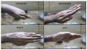
In operation, a gesture-controlled robot interprets the movements of the user's hand, detected by the transmitter. For instance, when the user turns their hand towards the front, the robot starts moving forward, maintaining this direction until a new command is received. Conversely, tilting the hand in the opposite direction prompts the robot to reverse its movement. Similarly, turning the hand left or right results in corresponding lateral movements by the robot. To halt the robot's motion, the user maintains a stable hand position.
The primary objective of this project is to utilize an accelerometer in conjunction with a Raspberry Pi Pico to regulate the movement of the robot based on hand gestures. Traditionally, robots function autonomously, responding to hand motions.
2. LITERATURE SURVEY
For a significant period, robotic vehicles have been operated via hand gestures, encompassing both transform and spatial domains. This section delves into various techniques explored in this domain.
Nitin Garg and Chirag Gupta proposed a method for controlling robots through gestures, also known as “gesture-controlled cars,” wherein manipulation occurs through hand gestures rather than conventional button pressing. Essentially, users wear a compact transmitting device equipped with an accelerometer-type sensor on their hand. Precise hand movements transmit instructions to the robot, enabling it to move in corresponding directions. The transmitting device integrates an encoder IC to encode four-bit data for communication via an RF transmitter, alongside a comparator IC for allocating appropriate voltage levels from the accelerometer inputs.
A technology developed by Archika et al. facilitates robot movement based on gesture detection utilizing accelerometer sensors. Accelerometers, primary technologies for human-machine interaction, offer excellent motion sensitivity across various applications. Motion technology enhances organic interaction with machines without necessitating adjustments due to mechanical equipment limitations. The affordability and compact size of accelerometers render them excellent tools for gesture detection and interpretation.
Ms. Asmita Jadhav presented the Hand Gesture Controlled Robot Using Arduino, introducing an Arduino-based system operated via single-hand gestures. The robot responds to hand movements detected by the accelerometer, enabling movement across four directions: left, right, forward, and backward. Human movements are detected using an infrared sensor with a 790nm wavelength range. Such robots find applications in industrial robotics, construction, and military sectors, particularly where conventional control methods via switches or remotes pose challenges or safety concerns.
Soubagya Nayak highlights the growing importance of human-computer interaction (HCI) amidst advancing computing and artificial intelligence landscapes. Traditional HCI methods involving mice and keyboards are perceived as mundane and restrictive. Improving quality of life for the elderly and physically challenged necessitates advancements in gesture control technology. The research aims to modernize HCI environments by eliminating traditional communication peripherals such as keyboards and mice, leveraging 3-axis accelerometer sensors and hand gesture control to operate robots.
3.COMPONENTS
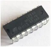
Motor Driver: – The L293D features two integrated H-bridge driver circuits, enabling the simultaneous operation of two DC motors in both forward and reverse directions. In its standard mode of operation, motor operations for both motors can be controlled via input logic at pins 2 & 7 and 10 & 15. When the input logic is set to 00 or 11, the corresponding motor will halt. For logic 01, the motor rotates counterclockwise, while for logic 10, it rotates clockwise. To initiate motor operation, the respective enable pins (I and 9) for the two motors must be set to high. Enabling the linked driver occurs when the enable input is raised to a high state, activating the outputs and ensuring their synchronous operation with the inputs. Conversely, the driver is disabled, and its outputs become inactive when the enable input is low.
DC motor: – A direct current (DC) motor comprises six fundamental components: axle, rotor (also referred to as armature), stator, commutator, field magnets, and brushes. Typically, high-strength permanent magnets are utilized to create the external magnetic field in most standard DC motors. The stator, a stationary element of the motor, includes the motor casing and one or more permanent magnet pole pieces. The rotor, in relation to the stator, rotates. The commutator is electrically linked to the windings forming the rotor, usually situated on a core. Upon power supply, the activated winding and the stator magnet(s) are misaligned due to the geometry of the brushes, commutator contacts, and rotor windings. Consequently, the rotor begins rotating until it nearly aligns with the stator's field magnets. As the rotor aligns, the brushes progress to the subsequent commutator contacts and energize the following winding. In the case of a two-pole motor, such as our example, rotation causes the current in the rotor winding to reverse, resulting in a “dip” in the rotor's magnetic field, further propelling the rotor's rotation.
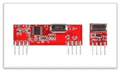
RF Transmitter: – For wireless control applications requiring short range and high-quality performance, the most suitable choice is the PLL-based ASK Hybrid 434 MHz RF transmitter module. This module incorporates a SAW-stabilized oscillator to ensure accurate frequency control, thereby optimizing performance across a wide range of frequencies. With a power source range of 3 to 12 volts, the transmitter is well-suited for battery-powered applications.
RF Receiver: – The modulated RF signal is directed into an RF receiver module for demodulation. There are two distinct types of RF receiver modules: super-regenerative receivers and super-heterodyne receivers. Super-regenerative modules typically utilize a series of amplifiers to extract modulated data from a carrier wave, particularly in low-power and cost-effective designs.
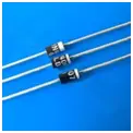
Diodes: – Diodes labeled as IN4001 through IN4007 have a maximum reverse bias voltage capacity of 50V and can handle a maximum forward current of 1 Amp. Diodes with similar capacity ratings are interchangeable. Furthermore, a diode with a higher capacity can be utilized as a substitute for one with a lower capacity, but the reverse is not permissible.
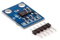
Accelerometer: – Accelerometers greatly enhance the user's perception of an object's surroundings. This compact device provides insights into horizontal motion, downward inclination, potential tipping points, and uphill movement. Among the various types of accelerometers, those leveraging the piezoelectric effect are particularly popular. This mechanism relies on small crystal formations subjected to acceleration forces, causing strain that generates a signal. This signal is then interpreted by the accelerometer to determine velocity and direction. Additionally, capacitance accelerometers operate by detecting alterations in capacitance between adjacent microstructures. When subjected to an acceleration force, movement of these structures leads to changes in capacitance, which the accelerometer translates into voltage for analysis.
4. WORKFLOW
Transmitter Section
The transmitter component of this project comprises a Raspberry Pi Pico, an ADXL335 accelerometer, and an RF receiver module.
The ADXL335 accelerometer generates output in the form of coordinates, which we can retrieve. While it is capable of providing coordinates in the x, y, and z-directions, we disregard the z-axis values by omitting its connection to the Arduino.
The transmitter's objective is to determine the tilt direction of the hand and transmit a corresponding message to the receiver. The x and y-axis values from the accelerometer serve as indicators for controlling the motor spin.
Since the x and y-axis pins of the ADXL335 output analog signals, they are linked to the analog pins of the Pi.
Within the while loop, we define the x-value and y-value as integers to store the received x-axis and y-axis values from the ADXL335 accelerometer. These integer values are then displayed on the serial monitor, followed by a 2-second delay before displaying the updated x-axis and y-axis values.
To establish the range for forward tilt, we capture a reading when the hand is slightly tilted and another reading when it's tilted to the maximum angle. These readings yield the range for both x and y coordinates.
Similarly, readings are taken for backward, right, left, and stationary tilts of the hand. Once the ranges for x and y in each position are recorded, we proceed to code the final implementation using MicroPython in Thonny IDE.
The initial step involves importing the virtual wire library, crucial for transmitting and receiving messages through the RF transmitter and receiver module. Three integers are defined: two for the analog x and y values, and one for LED13, the built-in LED. Pin 13 is set as an output.
In the void loop, the x and y values received from the ADXL335 accelerometer are assigned to respective variables. Utilizing if-else statements, the code determines the tilt direction based on predefined x and y ranges. For instance, if the x and y values fall within a specified range (e.g., xval>395 && xval<416) && (yval>360 && yval<380), indicating a forward tilt, the transmitter sends the letter “f” to the receiver. Similarly, for backward, right, left, and stationary tilts, the letters “b”, “r”, “l”, and “s” are transmitted respectively. Additionally, each time a signal is sent for forward, backward, left, or right tilts, the built-in LED at pin 13 is illuminated.
Receiver section
The transmitter segment is responsible for sending the corresponding letter to the receiver, contingent upon whether the hand is tilted backward, left-right, or stationary. Before the receiver can utilize this code and decode it, additional readings are required.
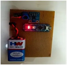
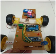
The receiver portion of this project includes an L293D motor driver, two motors, an RF receiver module, and a switch.
The L293D serves as a motor driver integrated circuit (IC), facilitating control over motor spin direction without requiring motor disconnection or polarity switching. The pinout diagram for the IC is provided with this documentation. Notably, the IC features two enable pins, which enable a particular side of the IC when set to a high state. The IC also encompasses four input pins and four output pins. Outputs one and two are linked to the terminals of one motor's battery, while outputs three and four connect to another motor's terminals. Input pins 1, 2, 3, and 4 interface with the Arduino, allowing the Arduino to signal the desired motor spin direction via these pins. To determine the necessary changes in input values for the motor to spin in the desired direction, a straightforward code is developed using the Thonny IDE. The code begins by assigning names to the pins connecting the Pico with the IC.
Next, we proceed to determine the input combinations for achieving various motor movements by digitally setting the values of inputs 1, 2, 3, and 4. We observe the combinations wherein both motors spin forward, both motors spin backward, one motor spins forward while the other remains stationary, and vice versa. This allows us to identify the input configuration required to execute specific maneuvers, such as making a right turn.
Following this process, we proceed to develop the final code. In this stage, we receive the letter transmitted by the signal from the transmitter. If the received signal corresponds to the letter ‘f', we set the input pins of the IC accordingly to enable forward movement of the vehicle. Similarly, the inputs are adjusted for backward, left, and right movements as required.
5. CONCLUSION
The aim of the system is to utilize a Raspberry Pi Pico to create a hand gesture-controlled car based on an accelerometer. It allows for straightforward movements to navigate the car in various directions, with the system's responsiveness adjustable to suit individual preferences.
Upon thorough examination of the system, it has been determined that as a person moves their hand in any of the four directions—Left, Right, Down, or Up—the accelerometer detects these changes and transmits corresponding signals through the following sequence: accelerometer → Raspberry Pi Pico → encoder → transmitter → decoder → motor driver → motor. This proposed method is applicable in environments with potential hazards, where a vehicle-mounted camera can provide user observation. Moreover, it finds utility in the medical field, particularly in the development of small robots assisting surgeons during surgeries.
An essential feature of the system is its real-time detection of palm gestures, facilitating intuitive and effective vehicle operation. Proper sensor installation enhances the vehicle's capability to detect individuals trapped under debris from earthquakes or landslides. Additionally, integrating a GPS device enables location tracking for the vehicle. Such a tool holds potential for military applications, enabling surveillance of battlefield areas devoid of human presence.